background image


7.5 

Removing and replacing the library controller 

To remove a library controller: 

Library controller is installed at the back of the library. Before you remove the library controller:  

1. 

Turn off power to the library (power button on the front panel). 

2. 

Remove the power cord cable. 

3. 

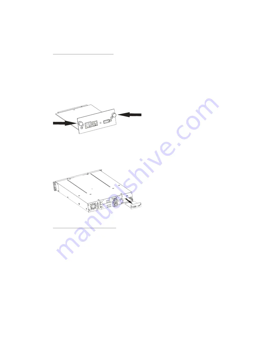
Loosen the two captive thumbscrews on the library controller (see Figure 58). 

Figure 58


Position of the two thumbscrews  


4. 

Pull straight back on the library controller to remove it from the library (see Figure 59). 

Figure 59


Library controller removal 


Replacing the library controller:


1. 

Unpack the new library controller from its package.  

2. 

Slowly insert the new library controller into the bay, and align the connectors on the library 
while supporting the controller assembly. 

3. 

Tighten the captive thumbscrews until the library controller is secure. 

4. 

Replace the power cord cable. 

5. 

Switch on power to the library (power button on the front panel). 

The library controller maintains a backup of all Critical and Configuration Data separate from the 
library controller, so that when replacing the library controller, the Critical and Configuration data can 
be maintained and will not have to be entered manually again.  When replacing a library controller, or 
a chassis FRU, there will be a mismatch between the data on the library controller and the backup 
data.  When such a mismatch is detected, the user will be requested to determine which set of data is 
correct.  

If the library controller has been replaced, then select “Identity data mismatch” to copy the 

backup data onto the library controller.  If the chassis FRU or Robotics FRU has been replaced 
(maintaining the original library controller), then select “Replace backup data” 

Summary of Contents for actiLib Autoloader 2U

Page 1: ...actiLib Autoloader 2U User and Service Guide Date September 17 2009 ...

Page 2: ...al or consequential damages including lost profits in connection with the furnishing performance or use of this material whether based on warranty contract or other legal theory actidata makes no representation or warranty with respect to the contents of this document and specifically disclaims any implied warranties of merchantability or fitness for any particular purpose Further actidata reserve...

Page 3: ...Contacting actidata Europe APAC actidata Storage Systems GmbH Wulfshofstrasse 16 44149 Dortmund www actidata com actidata Storage Systems GmbH Singapore www actidata com ...

Page 4: ...brary 2U Troubleshooting the actiLib Library 2U Upgrading and servicing the tape library Installing the Optional Remote Management Unit RMU Installing the tape library in a Rack Intended audience This guide is intended for system administrators and general users who need physical and functional knowledge of the actiLib Library 2U ...

Page 5: ...tive devices or micro circuitry Proper packaging and grounding techniques are necessary precautions to prevent damage NOTE Provides additional information Ventilation The product should be situated so that its location or position does not interfere with proper ventilation Heat The product should be situated away from heat sources such as radiators heat registers furnaces or other heat producing a...

Page 6: ...library fails because of accident misuse abuse neglect mishandling misapplication alteration faulty installation modification or service by anyone other than the factory service center or its approved agent The tape library is repaired by anyone including an approved agent in a manner that is contrary to the maintenance or installation instructions supplied by the manufacturer The manufacturer s s...

Page 7: ...moving the shipping lock 20 4 6 5 Rackmounting the library 22 4 6 6 Connecting the SCSI and power cable 24 5 Operating the tape library 27 5 1 Operating Modes 27 5 2 OCP Philosophy 27 5 3 Power Up Display 28 5 4 Note about the LED s 29 5 5 Input Modes 29 5 5 1 Selectable predefined values 29 5 5 2 Toggle values 29 5 5 3 Numerical values 30 5 6 Power ON OFF 30 5 7 OCP Menu Flow Charts 31 5 8 Partit...

Page 8: ...dia inventory 54 6 8 3 Releasing and replacing magazines 54 6 9 Service 55 6 9 1 Performing general library diagnostics 55 6 9 2 Determining and updating firmware 55 6 9 3 Rebooting the library 56 6 9 4 Viewing library logs 56 6 9 5 Cleaning tape drive s 57 7 Servicing the tape library 58 7 1 Possible tools needed 58 7 2 Electrostatic Discharge 58 7 3 Removing and replacing a tape drive 59 7 4 Rem...

Page 9: ...magazine 43 Figure 29 RMU login page 45 Figure 30 Identity library page 46 Figure 31 Identity drive page 46 Figure 32 Status library page 47 Figure 33 Status Drive page 47 Figure 34 Status Inventory page 48 Figure 35 Configuration System page 49 Figure 36 Configuration logical libraries page 49 Figure 37 Configuration license key page 49 Figure 38 Configuration Drive page 50 Figure 39 Configuratio...

Page 10: ...Figure 63 Releasing the magazine 73 ...

Page 11: ...iteria 18 Table 5 Status icons 45 Table 6 Troubleshooting table 66 Table 7 Access to manually release a magazine 73 Table 8 Removing the left magazine 73 Table 9 Main Error codes 75 actiLib Library 2U library physical specifications 80 Table 10 Operation specifications 80 Table 11 Tape library Environmental Specifications 81 ...

Page 12: ...you connect the library to an SE SCSI bus or if there are SE devices attached to the same SCSI bus the library s performance is limited to the maximum data transfer speed and maximum cable lengths of the SE bus For these reasons actidata strongly recommends that you do not use a SE SCSI bus with the library IMPORTANT Do not connect an LTO device to a SE SCSI bus as it will severely degrade perform...

Page 13: ... severely degrade performance and limit cable length Make sure that LUN scanning is enabled on the SCSI host adapter 4 4 2 Verifying the connection Depending on the server configuration you may need to change the SCSI IDs of the library When the host server is powered on install the software and or driver s that are compatible with the library Backup software packages may require additional softwa...

Page 14: ...magazines Led s and the mailslot Figure 1 Front panel overview Table 1 Front panel description Number Description 1 Triple Mailslot 2 Power button no power switch or button can be found on the back panel of the library 3 Front panel LED s Ready Activity Clean Drive Media Attention Error 4 Control keys Cancel Previous Next Enter 5 Magazin 6 Air vents 7 Front panel LCD screen ...

Page 15: ...error occurs A corresponding error message displays on the LCD screen see for more information OCP display consisting of 128 x 64 characters The OCP screen displays actions and status information menu items or error messages equivalent to the operation mode READY ACTIVITY Green LED The READY ACTIVITY LED is lit any time the unit is powered on and able to function It will blink whenever there is li...

Page 16: ...wn of the unit soft power down 4 5 3 Back panel overview The back panel of the library provides access to SCSI connectors tape drive bays the power connector Ethernet serial and the USB port Figure 3 Figure 4 and Figure 5 show the back panel of a library with a half height LTO tape drive a library with 2 half height LTO tape drive and a library with two half height LTO tape drives Figure 4 Back pa...

Page 17: ...ower connection 3 Tape drive tray 1 4 Tape drive tray 2 5 68 pin HD SCSI connectors 6 FC connector 7 Foil Product label 8 Drive LED 9 Ethernet port 10 Serial port 11 USB port Host 12 Shipping lock 13 SAS connectors 14 Power Supply LED s from top blue LED on AC connected green LED on Power good yellow LED on degraded Fan ...

Page 18: ...ccessible at all times Weight without media Single drive unit 14 7 kg Two drive unit 15 6 kg Weight with media Single drive unit 20 2 kg Two drive unit 21 1 kg Air quality The library should be placed in an area with minimal sources of particulate contamination Avoid areas near frequently used doors and walkways stacks of supplies that collect dust printers and smoke filled rooms Excessive dust an...

Page 19: ...r shipping damage If you notice any damage report it to the shipping company immediately 2 Open the box and remove the two rack rails if included and set aside 3 Carefully remove the shipping materials from the top of the library Remove the accessory package and set aside 4 Lift the library out of the carton and remove the bag from the library Remove the foam cushion from the back of the library S...

Page 20: ...on the rear panel right side of the library for future use see Figure 7 below To remove and store the shipping lock 1 Remove the yellow label that is securing the lock to the top of the library and then remove the lock see Figure 7 Figure 7 Shipping lock and label 2 1 2 Store the lock and label on the rear panel of the library see Figure 8 IMPORTANT If you are required to transport the library we ...

Page 21: ...Figure 9 Shipping lock before transportation 3 4 5 2 1 ...

Page 22: ...x screwdriver included in your shipment There are two sets of eight M6 screws in the accessory package that came with your library The type of rack that you have will determine the type of M6 screw that you will use To install the library 1 Determine the location in you rack for your library to be installed and using a pencil mark the location on each vertical rail in you rack 2 Using the screws f...

Page 23: ...crews included in the rack kit see Figure 11 step 2 5 Install the mounting brackets of the library using the 4 Torxs screws included in the rack kit Shown in Figure 11 step 3 6 With library guide pulleys and mounting brackets installed slide the library onto the rails 7 Secure the library to the rack see Figure 12 using a 3 Phillips screwdriver placed through the small holes in the mounting bracke...

Page 24: ...amage 3 an unapproved power cord could fracture resulting in the internal contacts being exposed which potentially could subject the user to a shock hazard Manufacturer disclaims all liability in the event a non manufacturer approved power cord is used CAUTION Failure to remove the power cables from these devices could result in damage to the library To connect the SCSI and power cable to the tape...

Page 25: ...of a SCSI cable to the remaining port and the other end to the next device on the SCSI bus Make sure that the last device on the SCSI bus in properly terminated Figure 14 Attaching the terminator to the LTO drive 5 Attach the power cable to the power connector on the back panel of the library see Figure 15 6 Plug the power cable into the nearest properly grounded power outlet Figure 15 Attaching t...

Page 26: ...8 Plug in the host server or workstation and all attached devices 9 Turn on any other devices you turned off earlier 10 Turn on the server ...

Page 27: ... 2 OCP Philosophy OCP operation must obey some basic rules These rules of operation constitute a philosophy Any operational conflict between commands received over SCSI or RMU and those entered via the front panel will be avoided with a reservation mechanism on a first come first served basis Any reservation by OCP is canceled by an OCP logout or the timeout which cancels the User Interaction Mode...

Page 28: ...g the Op Panel shall have appropriate information displayed to keep the user informed When the loader finishes coming alive it will display the current device status for a defined time or until a key is pressed After this initial status screen the home screen will be shown until a key is pressed This home screen shows the overall health of the loader indicating the status of the robotic and the co...

Page 29: ...issued by the drive The LED will be turned off again after a successful drive cleaning operation The Media Attention LED will indicate that there is a piece of media which is bad marginal or invalid The LED will be cleared when all marginal and invalid cartridges have been exported from the tape library The Error LED will be lit when there is an unrecoverable i e hard drive or tape library failure...

Page 30: ...ancel the whole edit process and the old value is valid again 5 6 Power ON OFF Part of the operator control panel is the Power On Off button Pressing this button will initiate a controlled Power Down of the unit soft landing The following operations will take place before the unit shuts down completely The display indicates with an appropriate message that the shutdown is in progress The library c...

Page 31: ...5 7 OCP Menu Flow Charts Figure 17 OCP User interaction Mode actiLib Library 2U ...

Page 32: ...Figure 18 Interaction Mode Information ...

Page 33: ...Figure 19 Interaction Mode Information continuation ...

Page 34: ...Figure 20 Interaction Mode Commands ...

Page 35: ...Figure 21 Interaction Mode Configuration ...

Page 36: ...Figure 22 Interaction Mode Configuration continuation ...

Page 37: ...Figure 23 Interaction Mode Service ...

Page 38: ...the logical libraries 5 8 1 Drive naming One full high drive is Drive 1 When using half high drives the first half high drive position will be called Drive 1 The second half high drive position will be called Drive 2 5 8 2 Mixing of drives The 2U library will support a mix of drives from different generations LTO2 LTO3 LTO in the same physical library and the same logical library They will also su...

Page 39: ...t possible life for your data cartridges follow these guidelines Use only the data cartridges that are designated for your model of library Clean the tape drive when the Clean Drive LED is illuminated Be sure to use only Ultrium Universal cleaning cartridges Do not drop a cartridge Excessive shock can damage the internal contents of the cartridge or the cartridge case itself making that cartridge ...

Page 40: ...ng of bar code technology can result in backup and restore failures To ensure that your bar codes meet manufactur s quality standards always purchase them from an approved supplier and never print bar code labels your self Ultrium tape cartridges have a recessed area located on the front of the cartridge next to the write protect switch Use this area for attaching the adhesive backed bar code labe...

Page 41: ...6 Barcode reader The barcode reader provides inventory feedback to the host application and or LCD screen by reading the cartridge barcode labels The library stores the customized inventory data in memory 5 9 7 Magazines Cartridges are stored in magazines Up to 12 cartridges can be stored in each magazine Magazines may be removed and inserted individually The actiLib Library 2U has two removable m...

Page 42: ...1 10 Mailslot 5 9 9 Mail slot Mailslots are used to import export individual cartridges without interrupting library operation The command to open the mailslot may be denied if the robotics is busy with some operation In that case Busy is displayed and the command has to be repeated once the robotics operation is finished See Figure 27 Figure 27 Handling mailslot Home Screen Next Enter Commands Me...

Page 43: ...Figure 28 Slot numbering right magazine ...

Page 44: ...ity page 46 Viewing static library information page 46 Viewing static drive information page 46 Status page 47 Viewing dynamic library information page 47 Viewing dynamic drive information page 47 Viewing the tape cartridge inventory page 48 Configuration page 48 Changing the system configuration page 48 Changing the drive configuration page 49 Changing the network configuration page 50 Changing t...

Page 45: ...ary is not capable of performing operations 6 4 Login CAUTION Some options of the RMU take the library offline This inactive mode can interfere with host based application software causing data loss Make sure the library is idle before attempting to perform any remote operations that will take the library offline To login select the access type and enter the correct password There are three levels...

Page 46: ...re Bootcode Firmware Revision IP Address Library Mode If the unit has more than one partition the properties of all logical libraries are displayed Figure 30 Identity library page 6 5 2 Viewing static drive information This page provides detailed information about the drive s No changes can be made from this page If a second drive is installed in the library Drive 2 information will be shown by se...

Page 47: ...ents The following information can be found on this page Status Cartridge in Operation Odometer Total Power On Time Robotic Status Magazine Left Magazine Right Mailslot Figure 32 Status library page 6 6 2 Viewing dynamic drive information This page provides detailed information about all drives that are present in the library Figure 33 Status Drive page ...

Page 48: ...7 1 Changing the system configuration As changes are made they will only be applied after the Apply Selections or the Submit button is selected After making the selection a warning page will inform the user of the impact of their proposed change In some cases a pop up screen will ask the operator to confirm their change Many changes will also require a reboot Changes that can be made are Library N...

Page 49: ...n the physical 2U library Figure 36 Configuration logical libraries page 6 7 3 Changing the license key This page if present allows the user to add additional functionality to the unit by entering license key information Please contact your supplier to see if this function is available in your model Figure 37 Configuration license key page ...

Page 50: ...gure 38 Configuration Drive page 6 7 5 Changing the network configuration This page shows the current network configuration of the library and allows modification to the configuration When a change is requested a pop up box will ask to confirm the changes A list of changes that can be made are DHCP Address checked On or unchecked Off when on static address not used IP Address Network Mask Gateway ...

Page 51: ...ted OCP Access PIN Code the password for accessing the OCP when the OCP Access PIN is enabled Repeat OCP Access PIN Code Enter the OCP Access PIN Code again Support Name the name of the individual within your company to contact for RMU or library support Support Phone the phone number of the individual within your company to contact for RMU or library support Support Email the email address of the...

Page 52: ... event notification are Notify Errors Select this item to be notified of library errors via email Notify Warnings Select this item to be warnings of library errors via email To E mail Address Enter the email address of the individual you would like to receive the errors and or warnings E mail Domain Enter the email domain name of the individual you would like to receive the errors and or warnings ...

Page 53: ...vital product data Figure 44 Configuration Restore defaults page 6 8 Operations 6 8 1 Moving media within the library This page allows the user to move tape cartridges within the library The source and destination are selected and then the move button in the center of the screen is clicked to activate the move Figure 45 Operations Move Media page ...

Page 54: ... 8 3 Releasing and replacing magazines This page allows the user to release the right or left magazine from the library Figure 47 Operations Magazines page NOTE To manually release a magazine see Removing and replacing a magazine on page 71 However this manual process should only be used if the magazine cannot be released using the Operator Control Panel or the Remote Management Unit ...

Page 55: ...g the test To cancel the test before it completes the cycles select the Stop button Figure 48 Service General Diagnostic page 6 9 2 Determining and updating firmware This page displays the current library and all drive firmware versions Firmware can be downloaded to the host then uploaded to the drive in the library by using this page CAUTION After a library upgrade the system restarts automatical...

Page 56: ...perform a library reboot There is a default time delay when the Web page refreshes itself This time should be sufficient to reload the page However during a reboot the connection to the library may be lost If the connection is lost the user will have to reload the page manually Figure 50 Service Reboot page 6 9 4 Viewing library logs This page allows the user to view the library logs after enterin...

Page 57: ...Figure 51 Service Library Logs page 6 9 5 Cleaning tape drive s This page allows the user to clean the tape drive s Figure 52 Service Clean drive page ...

Page 58: ...damage observe the following precautions 1 Transport products in static safe containers such as conductive tubes bags or boxes 2 Keep electrostatic sensitive parts in their containers until they arrive at static free stations 3 Cover the library with approved static dissipating material Provide a wrist strap connected to the work surface and properly grounded tools and equipment 4 Keep the work ar...

Page 59: ...53 Drive sled components of rear panel 2 Power down the library using the power button on the front panel see Figure 53 detail 1 3 The LED on the tape drive being removed is off Figure 53 detail 2 4 Remove the power cable SCSI cable and terminator if applicable from the tape drive being removed see Figure 53 details 3 4 and 5 5 Loosen the captive thumbscrews on the drive Figure 53 detail 6 IMPORTA...

Page 60: ...g the drive assembly see Figure 55 Figure 55 Installing a tape drive 2 3 1 3 Push the tape drive slowly into the drive bay until the drive seats itself against the back of the library NOTE If you are adding an additional tape drive to your library or if you are upgrading an existing drive be sure to use supported cabling configurations 4 Push the Product ID Foil back underneath the drive sled When...

Page 61: ...ure 56 Position of the three thumbscrews 4 Pull straight back on the power supply to remove it from the library see Figure 57 Figure 57 Power supply removal Replacing the power supply 1 Unpack the new power supply from its package 2 Slowly insert the new power supply into the bay and align the connectors on the library while supporting the power supply assembly 3 Tighten the captive thumbscrews un...

Page 62: ...mbly 3 Tighten the captive thumbscrews until the library controller is secure 4 Replace the power cord cable 5 Switch on power to the library power button on the front panel The library controller maintains a backup of all Critical and Configuration Data separate from the library controller so that when replacing the library controller the Critical and Configuration data can be maintained and will...

Page 63: ... anchoring the mounting brackets on the library to the rack These are captive screws and cannot be removed Remove your library from the rack using assistance 5 Remove the replacement library enclosure from the packing materials 6 Place the replacement library enclosure on a solid surface in preparation for installation in to the rack 7 Remove the mounting brackets and guide pulleys from your libra...

Page 64: ...e rack 20 Tighten the mounting bracket screws to anchor the replacement library enclosure to the rack 21 Plug in the power cord and host interface cable into the replacement library enclosure 22 Power on the library 23 Run the Library Verify test refer to OCP Service Library Verify 24 Securely package the library enclosure that was replaced and return to repair center ...

Page 65: ...maximum cable length reverts to the SE specification which for Ultra devices is 10 feet 3 meters for four or fewer devices and 5 feet 1 5 meters for more than four devices Termination If the library is the only SCSI device other than the SCSI host adapter on the selected SCSI bus it must be terminated Likewise if the library is physically the last SCSI device on the SCSI bus it must be terminated ...

Page 66: ...le 6 Troubleshooting table Problem Solution Power Library does not power on Check all power cord connections Make sure the power switch on the front panel is in the ON position Make sure there is power to the outlet Try another working outlet Replace the power cord Contact your service representative No display messages appear Make sure the power cord is connected Make sure the power switch is on ...

Page 67: ...an erase format or label operation on the cartridge Make sure you understand any data protection or overwrite protection schemes that your backup application may be using which could prevent you from writing to a given cartridge Retry the operation with a different known good tape Clean the tape drive See Cleaning the tape drive on page 57 Cleaning Cannot load the cleaning cartridge Make sure you ...

Page 68: ...aning the tape drive on page 57 for instructions Media Attention LED Issues Contamination by loose debris Avoid contamination by ensuring that the library is installed in a clean contamination free environment Cartridges should be stored vertically in their plastic cases Continue cleaning the tape drive as needed Non acclimated media A cartridge should be acclimated for at least 24 hours before be...

Page 69: ...ter cable or removes other devices from the bus Check for conflicting SCSI IDs Check that the HBA supports LUN scanning and this feature is enabled Device not properly terminated See Installation problems on page 65 Power on device before powering on the host computer Check that the device has been powered on and is not in an error state Check the SCSI connector for bent pins ...

Page 70: ...nel or the Remote Management Unit is still operational 1 Move the tapes from the drive s to the magazines using the Move Tape command or the Forced Drive Eject command See Moving tapes in the library on page 53 2 Use the magazine removal process to release the magazine and remove it from the library see Figure 60 To use the operator control panel see Unlocking removing and replacing magazines on p...

Page 71: ...inistrative password To remove a magazine 1 From the Home screen press Previous or Next on the OCP until the screen displays Operations 2 Press Enter to select 3 Press Previous or Next until the screen displays either Unlock Left Magazine or Unlock Right Magazine 4 Press Enter to select the desired magazine to unlock 5 Enter the Administrative password if requested 6 The display will read Left Mag...

Page 72: ...ment unit To login enter the correct password and press Enter Figure 61 RMU login page Go to Operations Magazines This page allows the user to release the right or left magazine from the library Figure 621 Operations Magazines page ...

Page 73: ...r the left and right magazine Table 7 Access to manually release a magazine Number Description 1 Right magazine release 2 Left magazine release 3 To manually release the magazines push the end of a straightened paper clip into the access hole for each magazine at the back of the library While holding the paper clip have a second person pull the magazine out of the front of the unit See Figure 63 F...

Page 74: ...ror by cycling power to the library and retrying the last operation If the error persists contact support personnel Support menu tree Example error code EVENT 6 A5 F1 Where Sequence number 6 indicates the position in sequence list 0 being the most recent Log shows a load error code A5 fan error sub code F1 caused by the fan at the back connector plate The event log with the library also includes a...

Page 75: ...port 86 Setting of elevator motor parameters failed Reset the unit and retry operation After several occurrences contact technical support 87 Setting of rotation motor parameters failed Reset the unit and retry operation After several occurrences contact technical support 88 Setting of sled motor parameters failed Reset the unit and retry operation After several occurrences contact technical suppo...

Page 76: ...rrences contact technical support 97 Sled outside range Sled has reached a position beyond the expected range Run Library Health Check after several occurrences contact technical support 98 Cartridge present sensor not found Run Library Health Check after several occurrences contact technical support 99 Sled home sensor not found Run Library Health Check after several occurrences contact technical...

Page 77: ...it and retry operation After several occurrences contact technical support C0 Network initialization failed Check network cable and network configuration If the error recurs contact technical support C1 Telnet Interface initialization failed Check network cable and network configuration If the error recurs contact technical support C2 Webserver initialization failed Check network cable and network...

Page 78: ... cartridge label Check barcode label on scratch cartridge and run Library Verify Test again If the error recurs contact technical support DB Warning event See section below DC I C Bus Failure Retry operation after several occurrences contact technical support DD Warning event See section below DE Warning event See section below DF Warning event See section below E0 Incompatible magazine detected C...

Page 79: ...ort F4 Drive Load Timeout Drive has run in a timeout while loading a tape The subcode indicates which drive is affected Retry operation if not successful contact technical support F5 Drive Unload Timeout Drive has run in a timeout while unloading a tape The subcode indicates which drive is affected Retry operation if not successful contact technical support ...

Page 80: ...MB s 288 GB hr Compressed 160 MB s 576 GB hr Drive type LTO half height FC drive 1 or 2 in 2U Number of slots 24 including mailslot MSBF w o drive 500 000 swaps Interface Fibre Chanel FC 4 Gb s actiLib Library 2U with LTO half height SAS drive Maximum storage capacity 24 data cartridges Native 19 2TB Compressed 38 4TB 2 1 compression Maximum data transfer rate Native 80 MB s 288 GB hr Compressed 1...

Page 81: ...pecifications Table 11 Tape library Environmental Specifications Characteristic Specification Temperature Operating 10º to 35º C Non operating 30º to 60º C Temperature shock immunity maximum rate of change 10º C per hour Humidity Operating 20 to 80 RH non condensing Non operating 20 to 80 RH non condensing ...

Page 82: ...vice may not cause harmful interference and 2 this device must accept any interference received including interference that may cause undesired operation Part 15 Class A of the FCC Rules is designed to provide reasonable protection against radio and television interference in a residential installation Although the equipment has been tested and found to comply with the allowed RF emission limits a...

Page 83: ... EN60950 EN55022 EN55024 EN61000 3 2 EN61000 3 3 VCCI This is a Class B product based on the standard of the Voluntary Control Council for Interference from Information Technology Equipment VCCI If this is used near a radio or television receiver in a domestic environment it may cause radio interference Install and use the equipment according to the instruction manual Manufacturer Responsible Part...

Page 84: ...tton 14 Power cable Remove 61 Replace 61 Power cord 24 25 Power On Self Test 25 PREVIOUS button location 16 R Rack stability 6 Rebooting library 56 Release magazine 54 73 Remote Management Interface RMI 44 Remove Library controler 62 magazine 41 tape drive 59 Removing a magazine Using Remote Management Interface 72 Removing stuck tapes 70 Replace library controler 62 Restoring factory defaults 53 ...

Reviews: