background image

www.acti.com

Hardware Manual 


22 

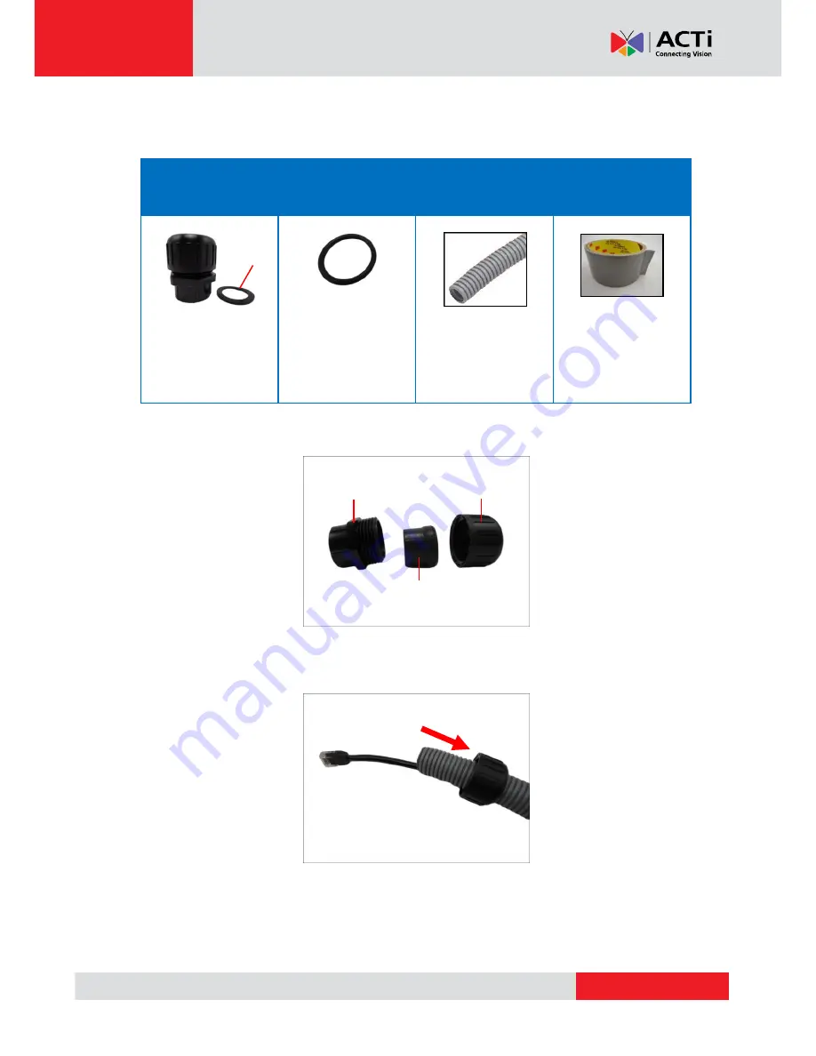
How to Waterproof the Cable Using the Conduit Gland 

1.


Prepare the following items:  

Cable Gland 

Gland Rubber Ring 

1/2” Flexible Conduit   

Waterproof Tape 


NOTE:

 The washer 

will not be used in this 
installation, please set 
it aside. 


NOTE:

 Not included 

in the camera 
package. 


NOTE:

 Not included 

in the camera 
package. 

2.


Detach the conduit gland as shown below. 


3.


Insert the Ethernet cable through the flexible conduit. Then insert the clamping nut through 

the flexible conduit. 


Gland Body 

Clamping Nut 

Sealing Rubber 

Washer 

Summary of Contents for KCM-8211

Page 1: ...Encoder Firmware V4 06 09 User s Manual Outdoor PTZ Camera Hardware Manual KCM 8211 2013 10 24...

Page 2: ...Camera 13 Mounting Options 13 Other Mounting Accessories 14 How to Mount the Outdoor PTZ 15 Step 3 Waterproof the Cable Connections 17 How to Waterproof the Cable Using the Cable Gland 18 How to Wate...

Page 3: ...www acti com Hardware Manual 3 Appendix 35 How to Connect Digital Input Digital Output Devices 35...

Page 4: ...attempt to service this video device yourself as opening or removing covers may expose you to dangerous voltage or other hazards Refer all servicing to qualified service personnel Trademarks All names...

Page 5: ...urning the equipment off and on the user is encouraged to try to correct the interference by one or more of the following measures Reorient or relocate the receiving antenna Increase the separation be...

Page 6: ...e personnel under the following conditions 1 When the power supply cord or plug is damaged 2 If liquid has been spilled or objects have fallen into the video product 3 If the inner parts of the video...

Page 7: ...www acti com Hardware Manual 7 Introduction List of Models This hardware manual contains the following model KCM 8211 2MP Outdoor PTZ Camera with D N Advanced WDR SLLS 18x Zoom lens...

Page 8: ...ome with the camera package If any of them is missing please contact your local sales agents or the Customer Help Desk CHD Camera Power Cord Power Adaptor Cable Gland Conduit Gland Gland Rubber Rings...

Page 9: ...ilt in amplifier Connecting an ordinary microphone will dwarf sounds and will result in inaudible recording 4 Ethernet Port The Ethernet port connects to a network using a standard Ethernet cable 5 Di...

Page 10: ...tton can be used for following purposes 1 The administrator s password has been forgotten and therefore the camera cannot be accessed 2 In case of IP address mask or allow deny filter related issues r...

Page 11: ...lastic cover 2 Loosen the four screws using the bundled Allen wrench 3 Carefully lift the camera cover and place it aside NOTE The cover is attached to the camera by a metallic wire do not abruptly li...

Page 12: ...www acti com Hardware Manual 12 5 Attach the camera cover Align the cover screws to the screw holes on the camera as marked on the illustration and secure the screws using the bundled Allen wrench...

Page 13: ...sories please visit our website http www acti com mountingselector Mount Types Accessories Pendant Mount Suitable when mounting the Outdoor PTZ on a hard ceiling PMAX 0102 Straight Tube w o Bracket PM...

Page 14: ...0503 PMAX 0305 PMAX 0503 Horizontal Pole Mount Suitable when mounting the Outdoor PTZ on a horizontal pole PMAX 0102 PMAX 0503 Corner Mount Suitable when mounting the Outdoor PTZ on a corner wall PMA...

Page 15: ...Install the Mounting Solution Check the Installation Guide for detailed information 2 Insert the Cable Insert the camera cables through the mounting tube e g gooseneck heavy wall mount straight tube...

Page 16: ...www acti com Hardware Manual 16 3 Mount the camera 1 Insert the top of the camera through the mounting tube 2 Secure the camera with screws...

Page 17: ...h a Cable Gland and Conduit Gland It is recommended to use one of these glands when a high PoE injector will be used with the camera However if the bundled power adaptor will be used or digital input...

Page 18: ...erior Grade Ethernet Cable Waterproof Tape NOTE The washer will not be used in this installation please set it aside NOTE Not included in the camera package NOTE Not included in the camera package 2 D...

Page 19: ...ing is completely aligned on the gap on the gland body 6 Attach the gland body to the Ethernet port of the camera IMPORTANT Make sure the rubber ring is completely aligned and flat on the gland body t...

Page 20: ...www acti com Hardware Manual 20 7 Connect the Ethernet connector to the Ethernet port of the camera 8 Insert the sealing rubber and claw into the cable gland body a b c d...

Page 21: ...rent types of waterproofing methods which may not be covered in this manual Check your installation environment and adapt a suitable waterproofing method If the camera is installed outdoors and the bu...

Page 22: ...rproof Tape NOTE The washer will not be used in this installation please set it aside NOTE Not included in the camera package NOTE Not included in the camera package 2 Detach the conduit gland as show...

Page 23: ...bber ring is completely aligned on the gap on the gland body 6 Attach the gland body to the Ethernet port of the camera IMPORTANT Make sure the rubber ring is completely aligned and flat on the gland...

Page 24: ...www acti com Hardware Manual 24 7 Connect the Ethernet connector to the Ethernet port of the camera 8 Insert the sealing rubber into the conduit gland body a b c d...

Page 25: ...waterproofing methods which may not be covered in this manual Check your installation environment and adapt a suitable waterproofing method If the camera is installed outdoors and the bundled power ad...

Page 26: ...in the package to house the cable connections 1 Place all the cables and the power adapter if using one inside the junction box Then secure the camera mount to the junction box 2 From the network powe...

Page 27: ...www acti com Hardware Manual 27 3 Secure the flex conduit fitting onto the junction box hole Note The PMAX 0700 Junction Box is not a bundled accessory Contact your sales agents to purchase...

Page 28: ...upplied power adaptor and power cord The Power LED of the camera will flash a few times and turn off as the camera mechanical components initialize Wait for the initialization to complete Once complet...

Page 29: ...the PC would request a unique IP address from the DHCP server automatically In such case the camera will immediately be ready for the access from the PC The user however might not know the IP address...

Page 30: ...ial numbers firmware versions etc and allows quick configuration of multiple devices at the same time The IP Utility can be downloaded for free from http www acti com IP_Utility When you launch IP Uti...

Page 31: ...o the network and it does not detect any DHCP services it will automatically assign itself a default IP 192 168 0 100 Whereas the default port number would be 80 In order to access that camera the IP...

Page 32: ...IP Utility With the procedure shown above all the cameras will have unique IP addresses starting from 192 168 0 101 In case there are 20 cameras selected the last one of the cameras would have the IP...

Page 33: ...Functionality Internet Explorer Live Video Yes Live Video Area Resizable Yes PTZ Control Yes Capture the snapshot Yes Video overlay based configuration Motion Detection regions Privacy Mask regions Y...

Page 34: ...in page The HTTP port number was not added behind the IP address since the default HTTP port of the camera is 80 which can be omitted from the address for convenience Before logging in you need to kno...

Page 35: ...panic button to the camera as such when the panic button is pressed the alarm signal will be sent through the camera Other common DI device applications are emergency button smoke detector passive inf...

Page 36: ...ound GND Blue Digital Input 2 DI2 Digital Output 1 DO1 Brown 12V DC Orange Digital Output 1 DO1 Digital Output 2 DO2 Green 12V DC Purple Digital Output 2 DO2 The table below shows the DI DO connection...

Page 37: ...nal power source In this case use the Black GND and the Red DI1 cables to connect a DI device and use the Brown 12V and the Orange DO1 cables to connect a DO device See wiring scheme below Consequentl...

Page 38: ...ake sure they match the above design The triggering circuit voltage has to be around 12V DC and the switch controlled circuit voltage has to match the external power supply e g 110V AC or 220V AC The...

Reviews: