


www.acti.com
Hardware Manual
23
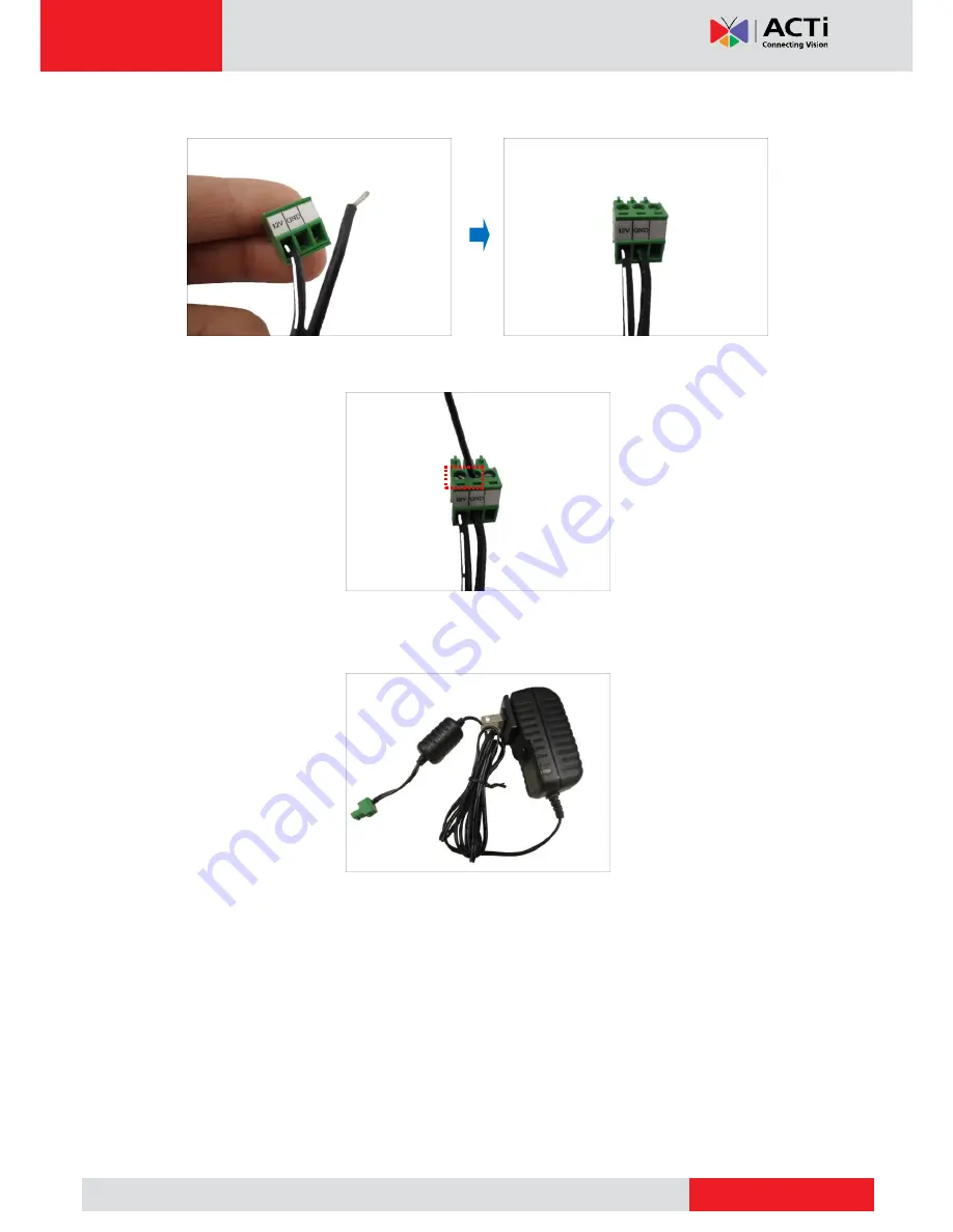
3.
Connect the wire with the white stripe to the
12V
pin and the other to the
GND
pin.
4.
Tighten the screws of the
12V
pin and the
GND
pins to secure the wire connection.
5.
Set the prepared power adapter for connection later. Below is an example of a power
adapter with an attached terminal block.
NOTE:
The power adapter is not bundled in the package.


