background image


A

A

C

C

T

T


WATER FILTRATION SYSTEMS


A

dvanced


C

leaning


T

echnology


FILTER OPERATIONS 

 
General:  The 1-Inch ACT Auto-Flush Filter uses Arkal Ring Disc filter media to remove 
suspended solids for fluids passing through the unit.  The filters require cleaning when 
they  become  loaded with  sufficient  solids to  inhibit  flow  causing  a  pressure  differential 
across the filter media of 5 psi to 7 psi.  The back flush controller actuates the auto-flush 
function when pressure differential reaches a predetermined set  point.  Another option 
uses time or time and pressure differential to initiate the back flush. 
 
Filter systems are arranged in 1 and 2 filter element systems.  The single filter unit uses 
a secondary screen filter to remove debris from the inlet water and protects the cleaning 
spray nozzles on the filter spine that supports the ring discs.  The multiple filter units are 
dependent  on  each  other  to  provide  clean  back  flush  water.    The  filter  controller 
sequentially  back  flushes  each  filter  for  the  pre-set  back  flush  cycle.    During  the  back 
flush,  no  water  is  allowed  to  discharge  from  the  filter  units  unless  equipped  with  a 
pressure-sustaining valve pilot. 
 
Operation:  
 
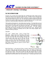
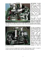
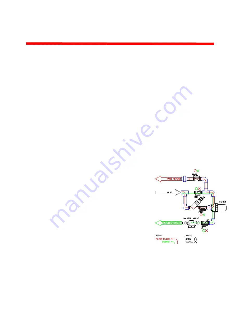
ACT  100S:    Filtration  Mode.    Refer  to  Single  Filter 
Illustration.    Water  enters  the  inlet  fitting  and  moves 
through  the  normally  open  valve.    Water  moves  through 
the  main  ring  disc  filter  and  discharges  through  the 
normally  open  outlet  valve  and  out  through  the  flow 
meter.    The  flush  and  flush  return  valves  are  normally 
closed  and  have  no flow  in  the  Filtration  Mode.    A  small 
continuous  cleaning  flow  from  the  secondary  flushing 
filter  returns  to  the  treatment  system  to  remove  debris 
caught by the screen. 


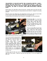
Back Flush Mode.  In the back flush mode, a 24 VAC signal is sent to both solenoids.  
This  action  causes  the  Inlet  and  Outlet  valves  to  close.    The  Flush  and  Flush  return 
valves open.  Incoming water is routed through the secondary screen filter and through 
the  Filter  Flush  valve.    This  action  causes  the  filter  disc  support  spine  to  lift  and 
simultaneously engages the spray nozzles to spin and clean the discs.  Debris and flush 
water flow from the main filter to the Flush Return valve.  The flush water returns to the 

Summary of Contents for ACT-100S

Page 1: ...ubsurface drip irrigation it is possible to quickly change dosing amounts in the controller if ponding occurs in any of the zones 5 No Size Limitation the size of standard absorption fields is limited by the need to increase depth of the lines for gravity flow ACT WFS installations are unlimited in size because pressure dosed effluent is applied uniformly throughout the dripper line matrix by pres...

Page 2: ...flow at pump start During back flushing filter valves are closed sequentially to back flush each element and the master valve is closed to concentrate all flow to the specific filter element being back flushed Drain field Equipment and Operation Equipment in the irrigated zones includes 1 2 diameter drip tubing buried 6 12 below grade PVC supply and return headers and mains one electric solenoid v...

Page 3: ...esidential and small commercial systems The ACT WFS Model ACT 100S is designed to protect subsurface drip tubing used for effluent dispersal by removing potential clogging agents The Bioline Dosing Management Controller monitors the system and regulates its operation The ACT Water Filtration System removes suspended solids so only those particles smaller than 100 micron may pass into the drip tubi...

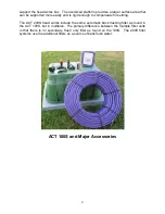
Page 4: ...tling The ACT 200S head works include the same automatic back flushing filter as found in the ACT 100S but in multiples The primary difference between the multiple filter units is that there is no secondary flush only filter as found on the 100S The 200S filter systems use the additional filters as a source of back flush water ACT 100S and Major Accessories ...

Page 5: ...ter for the pre set back flush cycle During the back flush no water is allowed to discharge from the filter units unless equipped with a pressure sustaining valve pilot Operation ACT 100S Filtration Mode Refer to Single Filter Illustration Water enters the inlet fitting and moves through the normally open valve Water moves through the main ring disc filter and discharges through the normally open ...

Page 6: ...ment system Typical flushing events last from 30 seconds to 2 minutes Once the filter back flush is completed the controller turns off the 24 VAC signal and the filter system returns to the Filtration Mode Tank Return Field Flush Backflush Filter Filter ACT 100S Inlet Supply Valve N O Field Flush Valve N C ...

Page 7: ...ial applications where reliability is a must The filter is equipped in a modular design Each filter is independent with regards to filter back flush Each filter side is equipped with a normally open and normally closed valve that reverse during filter back flush In addition the 200S is equipped with a master valve that closes during back flush and does not permit effluent flow to the dispersal fie...

Page 8: ...nds about 2 from the edge of the platform Prepare the site for the head works platform The unit can be installed so that it sits on the ground surface is partially buried or fully buried DO NOT cover the top of the head works box The unit requires occasional maintenance and must be left at or above the finished grade Be careful to set the final grade of the top of box so that grass and surrounding...

Page 9: ...ened to the skid and not allowed to carry any unsupported piping or other loads such as pumps OPERATION Note The following describes startup using the ACT Bioline Dosing Management System IF you are using a different dosing and filter flush controller you must follow the controller manufacturer s recommendations for operation Startup Startup is a critical operation where the system is tested witne...

Page 10: ...e Alarm button for more than 5 seconds or the controller will enter the programming mode Release the button and the pump will start The pump will run for the programmed dosing time and then go into a rest mode until time to start the next scheduled dose The alarm float can be tested in two ways It is recommended the test be done by raising the high water float by hand or with another object The fl...

Page 11: ...rned off and on again in the dosing mode as described under Testing and Inspection MAINTENANCE The components making up the ACT WFS ACT 100S dispersal system require limited maintenance and inspection The operator and or maintenance provider should inspect the entire system for potential leaks and component deterioration a minimum of two times per year The following should be performed each time t...

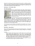
Page 12: ...re that the gray stack base remains firmly set in the filter body Be careful not to loose the compression spring on top of the disc stack It has two parts the spring and alignment button Place the rings on a small rope or length of braded wire Clean the rings with detergents and treat with a chlorine solution such as household bleach Agitate aggressively and rinse Inspect the rings and insure that...

Page 13: ... filter flush Carefully remove the flush filter cover by unscrewing the top Open the filter carefully and expose the screen filter element This is a course filter 50 30 mesh so the openings will appear fairly large Grasp the filter element carefully and pull it out of the filter housing Be sure that the spinner plate is attached Remove the plate from the housing if it fails to remain with the filt...

Page 14: ...screen and examine it for clogging A high pressure sprayer can be used to remove stubborn residues The finger filter can also be cleaned by soaking it in a detergent and chlorine combination which will help to remove and oxidize organic materials typical of primary effluent systems Use Teflon tape to seal the threads on the finger filter and reinstall the unit Be sure to reconnect the control tubi...

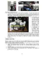
Page 15: ...be removed and cleaned This may be necessary on an annual basis especially if sunlight is present and encourages algal growth The return valve and air vacuum relief valve typically require no annual maintenance but should be observed for leaks or other outward problems TROUBLE SHOOTING System problems can occur that may cause the DRIP TECH system not to function properly Always begin by servicing ...

Page 16: ... option to repair or replace part or all of a defective product or refund part or all of the original purchase price if any part proves to be defective in material or workmanship after return of such product at customer s expense and after such return has been authorized in writing by JNM Technologies Inc THIS BASIC MANUFACTURER S LIMITED WARRANTY IS SUBJECT TO THE TERMS AND PROVISIONS IN SUBSECTI...

Page 17: ...LAIMS JNM TECHNOLOGIES INC SHALL NOT BE RESPONSIBLE FOR THE AFORESAID DAMAGES CLAIMS OR LOSSES DUE TO LATE DELIVERY OR DELIVERY OR NON DELIVER OR OTHERWISE THERE ARE NO WARRANTIES WHICH EXTEND BEYOND THE DESCRIPTION AS SET FORTH HEREIN IF JNM TECHNOLOGIES INC SHALL FURNISH TECHNICAL ADVICE OR ASSISTANCE WITH RESPECT TO THE PRODUCTS SOLD HEREUNDER IT SHALL BE GIVEN WITHOUT CHARGE TO BUYER AND SHALL...

Page 18: ...notice of claim offer JNM Technologies Inc in writing prompt opportunity to examine the defective product and correct the defect if possible This warranty shall be void unless buyer delivers the defective product to JNM Technologies Inc at buyer s sole cost and in accordance with JNM Technologies Inc s instructions ...

Reviews: