SERIES IP320 INDUSTRIAL I/O PACK 12-BIT HIGH DENSITY ANALOG INPUT BOARD
___________________________________________________________________________________________
- 7 -
ODD Byte
MSB
D07
D06
D05
D04
D03
D02
D01
LSB
D00
GSEL
1
GSEL
0
Not
used
SEL
HIGH
CH3
CH2
CH1
CH0
RESET CONDITION: all bits are undefined. Registers should be
programmed to the desired configuration before starting ADC analog
input acquisition.
Bit 15: When read, the CTRIG bit indicates whether an ADC
conversion has been triggered, either by software
command or external trigger input. If the bit reads high,
the conversion could be taking place or has been
completed. CTRIG is cleared by reading the ADC data.
Writing to this bit position will have no effect.
Bits 14-10: Not used - if read will return data written to those bit
positions.
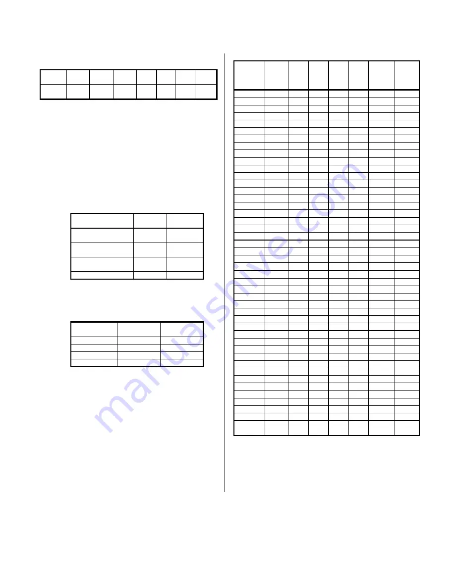
Bits 9 & 8: Control the input acquisition mode as described in the
following table:
Acquisition Mode
MODE1
Bit (D09)
MODE0
Bit (D08)
Differential Input
CH0-19 & CAL0-3
0
0
Single-ended Input
CH0-19
0
1
Single-ended Input
CH20-39
1
0
Auto Zero Input*
1
1
* Auto Zero input is enabled by the mode bits,
overriding all channel selection bits.
Bits 7 & 6: Control the programmable gain setting as described in
the following table:
Desired Gain
Setting
GSEL1
Bit (D07)
GSEL0
Bit (D06)
1
0
0
2
0
1
4
1
0
8
1
1
Bit 5: Not used - if read will return data written to the bit
position.
Bit 4: The SEL HIGH bit acts as the MSB for analog input
channel selection. As such, its action is grouped with
that of bits 3-0 (see following).
Bits 3-0: Control the selection of analog input channels per the
following table. Note that the SEL HIGH bit and MODE
bits are also shown to completely define the channel
selection. When MODE 1 & MODE 0 are both 0,
differential channels 0-19 and calibration voltages 0-3
may be selected; when MODE 1 is 0 and MODE 0 is 1,
single-ended channels 0-19 may be selected; when
MODE 1 is 1 and MODE 0 is 0, single-ended channels
20-39 may be selected; when both MODE 1 & MODE 0
are 1, the Auto Zero input is selected regardless of any
other bit levels.
Desired
Chan.
SEL
HIGH
Bit
D04
CH3
Bit
D03
CH2
Bit
D02
CH1
Bit
D01
CH0
Bit
D00
Mode
1
Bit
D09
Mode
0
Bit
D08
0
0
0
0
0
0
0
0/1
1
0
0
0
0
1
0
0/1
2
0
0
0
1
0
0
0/1
3
0
0
0
1
1
0
0/1
4
0
0
1
0
0
0
0/1
5
0
0
1
0
1
0
0/1
6
0
0
1
1
0
0
0/1
7
0
0
1
1
1
0
0/1
8
0
1
0
0
0
0
0/1
9
0
1
0
0
1
0
0/1
10
0
1
0
1
0
0
0/1
11
0
1
0
1
1
0
0/1
12
0
1
1
0
0
0
0/1
13
0
1
1
0
1
0
0/1
14
0
1
1
1
0
0
0/1
15
0
1
1
1
1
0
0/1
16
1
0
0
0
0
0
0/1
17
1
0
0
0
1
0
0/1
18
1
0
0
1
0
0
0/1
19
1
0
0
1
1
0
0/1
CAL0
1
0
1
0
0
0
0
CAL1
1
0
1
0
1
0
0
CAL2
1
0
1
1
0
0
0
CAL3
1
0
1
1
1
0
0
20
0
0
0
0
0
1
0
21
0
0
0
0
1
1
0
22
0
0
0
1
0
1
0
23
0
0
0
1
1
1
0
24
0
0
1
0
0
1
0
25
0
0
1
0
1
1
0
26
0
0
1
1
0
1
0
27
0
0
1
1
1
1
0
28
0
1
0
0
0
1
0
29
0
1
0
0
1
1
0
30
0
1
0
1
0
1
0
31
0
1
0
1
1
1
0
32
0
1
1
0
0
1
0
33
0
1
1
0
1
1
0
34
0
1
1
1
0
1
0
35
0
1
1
1
1
1
0
36
1
0
0
0
0
1
0
37
1
0
0
0
1
1
0
38
1
0
0
1
0
1
0
39
1
0
0
1
1
1
0
Auto
Zero
X
X
X
X
X
1
1
ADC Convert Command - (Write, Base + 10H)
The ADC Convert Command is a write only register (will not
respond to reads) that is used to trigger a conversion. The data
written to this location should be all ones to reduce digital noise,
although the write action alone is sufficient to trigger the conversion.
Execution of this command requires 0 wait states.


