INSTALLATION AND SERVICE INSTRUCTIONS
MODEL 310LD-MV
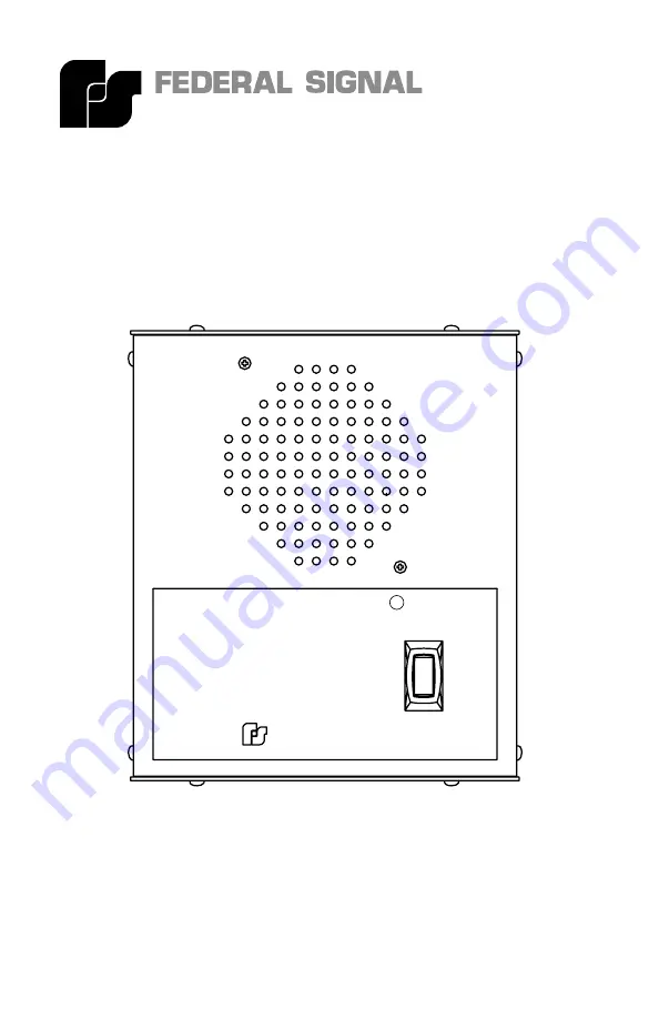
CALL
WARNING: DISCONNECT POWER BEFORE REMOVING COVER
UNIVERSITY PARK, IL. U.S.A.
FEDERAL SIGNAL CORPORATION
TALK
LISTEN
R
290A3077
Audio Master
2561328AREV. A 1108Printed in U.S.A.
Page 1: ...ION AND SERVICE INSTRUCTIONS MODEL 310LD MV CALL WARNING DISCONNECT POWER BEFORE REMOVING COVER UNIVERSITY PARK IL U S A FEDERAL SIGNAL CORPORATION TALK LISTEN R Audio Master 2561328A REV A 1108 Printed in U S A ...
Page 2: ... This is not a Listed safety device and is not intended to be used as such Read and understand all instructions before installing or operating this equipment Disconnect power before connecting or doing any mainte nance on this intercom All effective warning speakers produce loud sounds which may cause in certain situations permanent hearing loss You should take appropriate precautions such as wear...
Page 3: ...d see figure 1 The intercom comes from the factory set in the Master MAS mode In the Master mode the intercom acts as an amplifier constantly broadcasting over its speaker any signal that it receives on the signal lines Holding down the Listen Talk switch changes the unit from a speaker to a microphone see figure 2 The intercom will now trans mit over the signal lines to additional intercom s also...
Page 4: ...ore any installation maintenance or configuration changes are performed Move the J3 jumper block on the P C board from the MAS to SLA position see figure 1 This can be done using long nose pliers pull ing the block off the MAS and center position and placing it on the SLA and center position When hooked to a Master unit it may be necessary to override the Slave unit in order for the Master unit to...
Page 5: ... a remote sounder or light in order to ac cent the call feature The wiring diagram illustrates how an external light or horn can be wired in to augment the call tone See figure 7 The call signal is substantially louder than normal voice mes sages being carried on the line Do not depress the call switch while carrying on a conversation with someone on the system This will subject the listener to ve...
Page 6: ...d systems are avoided The polarity of the audio lines between the and signal terminals need not be maintained A shielded cable can be used in installations where extreme problems from interference are suspected The shield should always be connected to the ground of only one of the intercoms Connecting the shield to ground at both ends will cause ground currents to travel through the shield which c...
Page 7: ...ance 3400 ohms Max Output Voltage Sine Wave Balanced Output 15 Vrms Unbalanced Output 7 5 Vrms Square Wave Balanced Output 19 Vrms Unbalanced Output 9 5 Vrms Speaker Rating 2 watts Speaker Impedance 8 ohm Temperature Range 31 F to 150 F 35 C to 66 C Fuse Type GMC 1 2 1 2 amp 250 V Call Switch Contact Rating 400 mA at 125 Vac 1 25 amp at 24 Vdc Agency Approvals UL CSA Weight Shipping 3 lb 9 oz Net ...
Page 8: ... intercom is intended to be mounted on any relatively flat and rigid surface by the four mounting holes in the interior of the housing Figure 4 is a dimensional outline drawing showing the proper mount ing configuration The four mounting holes are 202 in diameter and are designed to accept a 10 mounting screw Hardware for mounting the intercom to the surface is left up to the installer The interco...
Page 9: ...r position There is a switch on the board in the Class I wiring compartment to configure the operation of the board from 120VAC to 240VAC The switch is factory set for the intercom to operate on 120VAC see figure 3 See figures 5 through 12 for typical intercom configurations F SERVICE Any maintenance must be performed by a trained electrician in accordance with NEC guidelines and local codes 1 Gen...
Page 10: ...ts Replace fuse with GMC 1 2 only DO NOT substitute Description Part Number Resistor 1K 1W K101216 Fuse GMC 1 2 K148A155 Mini jumpers K139A209 PCBA K2001290 Switch K122283 Speaker K132141 8 00 FRONT BACK BOTTOM CLASS I WIRE ENTRY CLASS II WIRE ENTRY 6 87 3 50 COMBINATION 1 2 3 4 KNOCK OUT 3 05 1 40 7 125 5 50 290A3079 4 x 202 CALL WARNING DISCONNECT POWER BEFORE REMOVING COVER UNIVERSITY PARK IL U...
Page 11: ...ces the Slave into the listen mode and the Master into the talk mode The MAS SLA jumper must be placed in the SLA mode for this operation on the slave unit Using Foot Switches Using normally open simple contact closure foot switches customer supplied allows for total hands free operation of the listen talk functions Figure 6 290A3081 24 VDC GROUND REMOTE AUDIO AUDIO DRY CONTACT DRY CONTACT 24 VDC ...
Page 12: ... CONTACT NEUTRAL HOT EARTH GND NEUTRAL HOT EARTH GND INTERCOM I 310LD MV MASTER J7 J2 J2 J7 INTERCOM II 310LD MV SLAVE USING CALL DRY CONTACTS WITH AC 1K 1 WATT 7 6 5 4 3 2 1 3 2 1 3 2 1 7 6 5 4 3 2 1 POWER POWER AC AC No Remote Power Available Intercom I supplies the DC power to the second intercom Earth ground must be wired on the second unit Figure 8 290A3083 24 VDC GROUND REMOTE AUDIO AUDIO DR...
Page 13: ...BASIC BALANCED LINE SYSTEM 1K 1 WATT 7 6 5 4 3 2 1 3 2 1 3 2 1 7 6 5 4 3 2 1 AC AC Shielded Balanced Line System This system offers maximum isolation from noise over long runs The shield should only be grounded at one side AC power is utilized at both sites The unit is factory configured for balanced line operation NOTE both jumpers in BAL position Figure 10 290A3085 24 VDC GROUND REMOTE AUDIO AUD...
Page 14: ...d only be used when hooking to existing devices The neighboring jumpers on the circuit board must be changed from the BAL position to the UNB position for these installations see figure 1 290A3086 24 VDC GROUND REMOTE AUDIO AUDIO DRY CONTACT DRY CONTACT NEUTRAL HOT EARTH GND INTERCOM I 310LD MV MASTER J7 J2 BASIC UNBALANCED LINE SYSTEM 1K 1 WATT 7 6 5 4 3 2 1 3 2 1 AC AUDIO GROUND CABLE AC Figure ...
Page 15: ... REMOTE AUDIO AUDIO DRY CONTACT DRY CONTACT NEUTRAL HOT EARTH GND NEUTRAL HOT EARTH GND INTERCOM I 310LD MV MASTER J7 J2 J2 J7 INTERCOM 2 310LD MV SLAVE MULTIPLE INTERCOMS 1K 1 WATT 7 6 5 4 3 2 1 3 2 1 3 2 1 7 6 5 4 3 2 1 AC AC AC DRY CONTACT DRY CONTACT AUDIO AUDIO REMOTE GROUND 24 VDC NEUTRAL HOT EARTH GND DRY CONTACT DRY CONTACT AUDIO AUDIO REMOTE GROUND 24 VDC NEUTRAL HOT EARTH GND INTERCOM 3 ...
Page 16: ...back page ...