background image

Designer Flueless Fires

INSTALLATION & USERS INSTRUCTIONS

X-ERO Traditional & Contemporary

Product Codes 

XF-EROT-F - Traditional Gunmetal Frame

Leave with the User

Acquisitions of London

24-26 Holmes Road

London NW5 3AB

Tel: 0044 (0)207 482 2949

Email: [email protected]

X-ERO

Summary of Contents for X-ERO

Page 1: ... USERS INSTRUCTIONS X ERO Traditional Contemporary Product Codes XF EROT F Traditional Gunmetal Frame Leave with the User Acquisitions of London 24 26 Holmes Road London NW5 3AB Tel 0044 0 207 482 2949 Email sales acquisitions co uk X ERO ...

Page 2: ...ooklet is owned by Acquisitions of London You are not permitted to copy or adapt any of the content without the prior written permission of Acquisitions of London The products covered by this booklet are protected under patents GB2275331B and GB2413178B 2011 Acquisitions of London X ERO Traditional Gunmetal Frame ...

Page 3: ...alls to become discoloured This appliance is intended as a secondary source of heat only and should not be used in a room without some form of background heating present If the appliance is used in a room as the sole source of heat then condensation may occur on colder surfaces within the room On first light up of a new appliance initial curing of high temperature paint and burning off of lubrican...

Page 4: ...ctronic carbon monoxide detector complying with the current edition of BSEN 50291 must be installed in the same room as the appliance For maximum safety it is recom mended that such device is continuously mains powered and arranged in such a way that the gas sup ply to the appliance is isolated in the event of an alarm The selection and installation of such device shall be in accordance with the c...

Page 5: ...ny kind If the room in which the appliance is to be installed is carpeted or has a fabric floor covering then a small solid hearth will be required meeting the dimensions specified in table 1 and illustrated in figure 2 In all installations the wall or back panel of the installation must be flat non combustible and meet the dimensions specified in table 1 and illustrated in figure 2 The appliance ...

Page 6: ...mm 4 but curtains drapes and other fabrics are not permitted within a distance of 500mm 20 of the appliance sides No such materials are permit ted directly above the appliance regardless of distance The minimum clearance to the ceiling above the appliance is 800mm 31 5 measured from the top of the appliance glass panel Combustible materials should not be positioned directly in front of the applian...

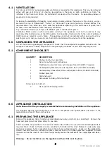
Page 7: ...g materials at your local recycling centre COMPONENT CHECKLIST APPLIANCE INSTALLATION Note Ensure that the gas supply is isolated before commencing installation of the appliance The fireplace opening and environment must be in compliance with specifications laid down in the appropriate sections of these instructions PREPARING THE APPLIANCE Remove the appliance from its carton as described previous...

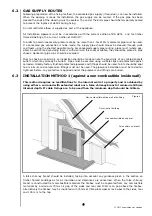
Page 8: ...ied Pipes must be secured using suitable clips and protected against corrosion Ideally factory finished protected pipework and fittings should be used Joints should be kept to a minimum and compression fittings must not be used The pipework installation must be tested for tightness before any protection is applied and or the pipework and fittings are buried INSTALLATION METHOD 1 against a non comb...

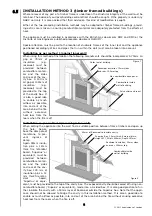
Page 9: ...n and squarely over the fireplace opening and if possible centrally under a block joint Clear out the block work in the area and insert the lintel by saw or stitch drill and chisel Do not dry bed the lintel always bed on mortar and securely slate pin Clear out the block work from below the lintel to form the opening for the firebox to be inserted The top of the exposed area of cavity must be seale...

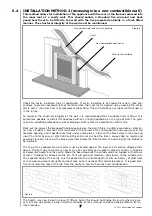
Page 10: ...ssible into and out of the area behind the fire without excessive heat loss from the room when the fire is off Installation as per method 2 recessing into a wall When setting the appliance into the wall find a suitable position between frame timbers and open up the hole Secure back the damp proof membrane to pre vent ingress of damp Again 50mm insula tion plus a 12mm thick fire retardant board Sup...

Page 11: ...plied to the gas pipe Secure the firebox by inserting screws in the previously prepared locations if screw fixing or refer to the following section if cable fixing CABLE FIXING When using this method for fixing the minimum depth of the opening must be increased from 105 mm to 125 mm This is to allow for the eyebolts and a space for the cable tensioning Remove the appliance glass panel by removal o...

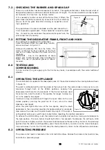
Page 12: ...e control knob onto the valve spindle as shown in figure 14 The pilot is visible behind the left hand side of the burner Push the control knob in fully and turn anti clockwise through both of the SPARK positions keeping fully depressed hold there for a few seconds If the fire has not been used for some time hold the knob in this position for longer to allow any air in the pipes to be purged Contin...

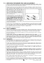
Page 13: ...ecommend that a guard be used for the protection of young children pets the elderly and the infirm SERVICING Isolate the fire from the gas supply Ensure that the fire is fully cold before attempting service A sug gested procedure for servicing is detailed below 1 Lay out the dustsheet and tools 2 Remove the hood two M6 screws and front and frame facia 3 Remove the glass door assembly four M6 screw...

Page 14: ...EVER MODIFY OR BEND THE THERMOCOUPLE TO MAKE THE PILOT STAY ALIGHT If the pilot will not stay lit there is a problem with dirt the gas supply or the thermocouple needs replacement Modifications are dangerous and can have a serious unseen effect on safety and therefore MUST not be done Replacements must be original manufacturers parts Re assemble in the reverse of removal Ensure operating pressures...

Page 15: ...m the top of the appliance but none should emerge from the joints or gasket faces especially around the door It is important to note that the appliance can never be expected to be 100 smoke tight and small quantities of smoke may be seen in corners of joints and gasket faces etc without affecting safety when the fire is in operation TROUBLESHOOTING GUIDE Fire sparks but pilot does not light No gas...

Page 16: ...T Pilot flame shrinks Poor gas flow to fire check pressure with fire on high when fire is on high If pressure is low remove any restriction in pipework or valve Check all isolators are adequately sized and fully open Check meter pressure is adequate If the pilot will not stay lit there is a problem with dirt the gas supply or the thermocouple needs replacement Modifications are dangerous and can h...

Page 17: ...rol panel Combustible items such as flooring and furniture and soft wall coverings such as blown vinyl or embossed paper low temperature surrounds etc may discolour if fitted too close to the fire See rel evant section for further details on clearances to combustibles No combustible materials or flooring should protrude onto the hearth if fitted This appliance incorporates a combustion monitoring ...

Page 18: ...nt of the appliance within a distance of one metre A combustible shelf may be fixed to the wall above the fire providing that it complies with the dimen sions given below The shelf depth may be greater but the height must also be increased accordingly An increase in height of 25mm is required for every 12 5mm of additional shelf depth For shelves that are too low protec tive devices can be used su...

Page 19: ...rol knob clockwise to the low setting To turn to the pilot only position from the HIGH or LOW positions press the control knob in and return to the nine o clock posi tion and release To turn the fire OFF keep the knob pressed in return to the off position and release COMBUSTION MONITORING SYSTEM This fire is fitted with a combustion monitoring safety device ODS If the fire shuts down during use fo...

Page 20: ...T PARTS The Installation instructions carry full servicing details for the use of the installer PART NO ITEM F550272 Glass door assembly F550234 Hood Please enquire Firefront F730085 Gas valve F730023 Pilot assembly F510035 Burner unit F780079 Catalyst seal kit must also be supplied F940136 Seal kit for Catalyst 4 8 0 9 0 As our policy is one of continuous improvement and development we hope there...

Reviews: