


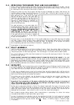


SERVICING THE BURNER TRAY AND GAS ASSEMBLY
Firstly, remove the hood and front fret/facia, the glass panel (Euphoria and Blenheim models : remove
ceramics), data plate and disconnect the gas connection at the isolator elbow. Remove the burner tray
by removing the four securing screws shown in figure 15.
Remove the pilot and main burner pipes and blow through to dislodge any debris. Now remove the
restrictor elbow and blow through to make sure it is entirely clear. Unclip the pilot lint gauze and clean
with a soft brush. Clean the exterior of the
pilot assembly with a soft brush and blow
through the flame ports on the pilot head.
Check the aeration holes are free from lint or
dirt. The pilot assembly can be removed if
required by disconnecting the electrode HT
lead, gas pipe and unscrewing the mounting
screws and lifting away.
The pilot assembly is a non-serviceable item
and should not be taken apart. Aeration holes
must be absolutely clear internally for proper
operation.
NEVER MODIFY OR BEND THE
THERMOCOUPLE TO MAKE THE PILOT
STAY ALIGHT
. Modifications are dangerous
and can have serious unseen effects on safety.
If the pilot will not stay lit there is a problem
with dirt, the gas supply to it, or the thermo-
couple needs replacement.
The gas valve is a non-serviceable item. If this needs replacement, remove M15 securing nut holding
the valve in place, remove all pipe unions, electrode lead, thermocouple lead and then the complete
valve. Replacement must be original manufacturers parts. Re-assembly is the reverse of removal.
Ensure operating pressures are as stated in Section 2; Appliance Data.
Re-assembly in the reverse of removal.
PILOT ASSEMBLY
Clean the pilot assembly with a soft brush and blow through. Check the aeration holes are free of any
dirt or lint. Clean thoroughly internally, the connection can be removed from the base of the pilot unit
using two spanners to make cleaning easier. Do not damage or try to dismantle the pilot injector.
The unit is factory set and the only check necessary is to ensure the spark gap is correct. See speci-
fications for gas setting.
NEVER MODIFY OR BEND THE THERMOCOUPLE TO MAKE THE PILOT STAY ALIGHT
. If the pilot
will not stay lit there is a problem with dirt, the gas supply, or the thermocouple needs replacement.
Modifications are dangerous and can have a serious unseen effect on safety and therefore MUST not be
done. Replacements must be original manufacturers parts. Re-assemble in the reverse of removal.
Ensure operating pressures are as stated in Section 2; Appliance Data.
CATALYST
It is recommended that the catalytic converter is inspected for signs of damage and dirt during routine
servicing procedures. The expected life of the catalyst is in excess of 11,000 hours (10 years of normal
use). After this time the catalytic converter should be replaced.
If there are any deposits of dirt or soot on the catalyst they should be cleaned with a soft brush and a
vacuum cleaner. If removed for cleaning ensure the seals are in good condition before replacing the cat-
alytic converter. New seals will usually be required.
The performance of the catalysts may be checked using a combustion gas analyser as follows. Any
analyser used should conform to EN 50379-3. A suitable analyser is a Telegan Sprint 2000 XT
Combustion Flue Gas Analyser.
Important: The temperature of the gases emitted by the catalytic converter is in excess of
400
o
C. Measuring gas of this temperature may damage some types of gas analysers. If in
doubt consult the equipment manufacturer.
Position gas sample probe directly in front of the catalyst underneath the hood, in the centre of the
upper firebox. Ignite the fire as per the operating instructions, and run at high setting for 15 minutes.
Record the carbon dioxide (CO2) concentration and then the carbon monoxide (CO) concentration as
displayed by the analyser - also noting the units in which the values are expressed.
Most analysers display carbon dioxide (CO2) concentrations in percentage (%) terms and carbon
monoxide concentration in parts per million (ppm) terms.
In order to calculate the combustion ratio for the appliance (CO/CO2) it is first necessary to express
both gas concentrations in terms of percentage. To convert from parts per million (ppm) to a percent-
age (%) divide the ppm figure by 10,000. Examples : 35ppm = 0.0035%, 15ppm = 0.0015%, 5ppm
= 0.0005%.
12
9.2
9.3
9.4
©
2011 Acquisitions of London
Figure 15