- 36 -
5.1.3 ADC calibration (Auto color balance adjustment)
~~Analog only, it is not required for DVI-D input source
1. Setup input timing ICL-605( 1280x1024@75Hz ), pattern 42(5-Mosaic pattern with white
color block) with Analog signals from Chroma video pattern generator. (it depends on Scaler
IC supplier’s recommendation)
2. Enter factory mode (press “Empowering” & “Power” buttons at the same time to turn on
monitor).
3. Move cursor into “Burn-in Mode” tag and select “On” to enable burn-in mode.
4. Close OSD menu then press “Auto” button for auto color adjustment. (This procedure will get
optimal gain/offset(clamp) values)
5. Checking if the picture is ok, or reject this monitor and check its circuit board or wire/cable
connection.
5.1.4 Color temperature adjustment
1. Setup input timing to any preset modes, pattern 41(full white color pattern) with Analog
signals from Chroma video pattern generator.
2. Enter factory mode (press “Empowering” & “Power” buttons at the same time to turn on
monitor).
3. Move cursor into “Burn-in Mode” tag and select “On” to enable burn-in mode.
4. Make sure ADC calibration (auto color balance adjustment) had already been done.
5. Measure color temperature by Minolta CA-110 (or equivalent equipment).
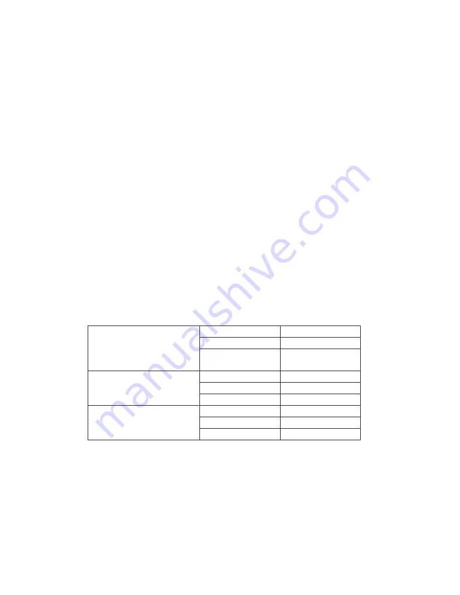
6. Adjust the color temperature ~~ Two methods can be used to adjust RED, GREEN, BLUE
value of each color temperature, C0/Cool, C1/User & C2/Warm to meet following spec
requirement, the 1
st
method is by using external PC and IIC alignment protocol to do
automatic adjustment, and the 2
nd
method is by manually and must be in factory mode.
X+-
0.283+(-) 0.03
Y+-
0.297+(-) 0.03
Color temperature
(C0/cool on OSD)
Luminance
X+-
Y+-
Color temperature
(C1/User on OSD)
Luminance
X+-
0.313+(-) 0.03
Y+-
0.329+(-) 0.03
Color temperature
(C3/Warm on OSD)
Luminance
7. Move cursor into “Burn-in Mode” tag and select “No” to disable burn-in mode.
8. Turns off the monitor power.
5.1.5. Writing EDID data into monitor
1. Setup a PC with DDC card.
2. Connect PC to monitor with a D-sub signal cable.
3. Please refer to the Q212 for the correct EDID file.
4. Runs the writing program to write the analog EDID data into EEPROM for analog input(ie.
15-pin D-sub).
Summary of Contents for X203H
Page 22: ... 22 ...
Page 42: ... 42 5 3 EDID Upgrade Procedure Step 1 Run the program Q EDID V012 exe when the UI popped up ...
Page 45: ... 45 Step 5 If read EDID is successful it shows Read EDID OK ...
Page 46: ... 46 5 4 OSD Operation Guide ...
Page 47: ... 47 ...
Page 48: ... 48 ...
Page 49: ... 49 ...
Page 50: ... 50 ...
Page 53: ... 53 6 1 3 Check Scalar ...
Page 55: ... 55 6 1 5 Power Board no work troubleshooting ...
Page 56: ... 56 6 1 6 Audio Function ...
Page 67: ... 67 Fig 2 Appearance Description ...
Page 68: ... 68 Appendix 3 Interface Board ...
Page 69: ... 69 ...
Page 70: ... 70 ...


