


System Utilities
2-15
AMI UEFI BIOS Flash SOP for DOS
0
Flash UEFI BIOS SOP for DOS,
1. Please make a DOS bootable device.
2. Copy BIOS folder (ex: aParis-H61_D01 folder) into DOS bootable device.
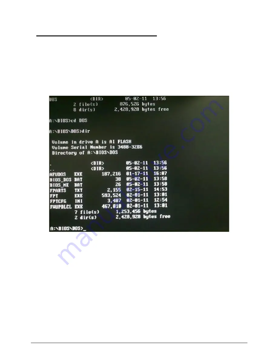
3. Boot to DOS mode and enter the BIOS folder.
4. Enter to the DOS folder under BIOS folder.
5. Flash Method.
- For end-user only. Currently, all ODMs should NOT use it to flash SBIOS.
It will cause unexpected problem since some BIOS block data maybe different between old
and new BIOS.
- It will keep DMI and setup settings.
- QTC team can simulate user's behavior by using it.
1) Execute “
BIOS_DOS.bat
” file.
Summary of Contents for Veriton Z4621G
Page 1: ...Acer VZ4620G VZ4621G SERVICEGUIDE ...
Page 2: ...ii ...
Page 6: ...vi ...
Page 7: ...vii ...
Page 8: ...viii ...
Page 9: ...CHAPTER 1 Hardware Specifications ...
Page 28: ...1 20 Hardware Specifications and Configurations M B Placement 0 ...
Page 30: ...1 22 Hardware Specifications and Configurations Internal header pin definition 0 ...
Page 31: ...Hardware Specifications and Configurations 1 23 Block Diagram 0 ...
Page 32: ...1 24 Hardware Specifications and Configurations ...
Page 33: ...CHAPTER 2 System Utilities ...
Page 50: ...2 18 System Utilities 8 Flash BIOS is finished ...
Page 54: ...2 22 System Utilities 10 Flash BIOS is finished ...
Page 63: ...System Utilities 2 31 12 Select Yes and press Enter key 13 Flash BIOS is finished ...
Page 66: ...2 34 System Utilities 11 Select Yes and press Enter key 12 Flash BIOS is finished ...
Page 69: ...System Utilities 2 37 ...
Page 73: ...System Utilities 2 41 ...
Page 74: ...2 42 System Utilities ...
Page 75: ...CHAPTER 3 System Disassembly and Assembly ...
Page 78: ...3 4 ...
Page 86: ...3 12 System Disassembly and Assembly First open one top side then open the other top side ...
Page 87: ...System Disassembly and Assembly 3 13 Open the low side ...
Page 96: ...3 22 System Disassembly and Assembly Removing the Display Card 0 ...
Page 113: ...System Disassembly and Assembly 3 39 ...
Page 121: ...System Disassembly and Assembly 3 47 Unplug the LCD power cable Take out the LCD with bracket ...
Page 131: ...System Disassembly and Assembly 3 57 Lock all the latch Plug the LVDS cable ...
Page 141: ...System Disassembly and Assembly 3 67 Close the CPU bracket cover ...
Page 147: ...System Disassembly and Assembly 3 73 Lock 2 VGA locks ...
Page 153: ...System Disassembly and Assembly 3 79 Attach the mylar to cover the camera ...
Page 160: ...3 86 System Disassembly and Assembly 4 Attach the mylar as the location shown in the picture ...
Page 164: ...3 90 System Disassembly and Assembly N A 4 Table 3 45 ID Size Quantity Screw Type ...
Page 170: ...3 96 System Disassembly and Assembly Install the hinge cover ...
Page 171: ...System Disassembly and Assembly 3 97 Thermal Pad location on base pan 0 ...
Page 174: ...3 100 System Disassembly and Assembly ...
Page 175: ...CHAPTER 4 Troubleshooting ...
Page 190: ...4 16 Troubleshooting Pressing the 25 calibration points in proper hole by using the stylus ...
Page 194: ...4 20 Troubleshooting ...
Page 195: ...CHAPTER 5 Jumper and Connector Locations ...
Page 196: ...5 2 Jumper Setting 5 4 Setting Jumper 5 4 ...
Page 197: ...Jumper and Connector Locations 5 3 Jumper and Connector Locations ...
Page 200: ...5 6 Jumper and Connector Locations ...
Page 201: ...CHAPTER 6 FRU List ...
Page 202: ...6 2 VZ4620G VZ4621G Exploded Diagrams 6 4 FRU List 6 7 ...
Page 204: ...6 4 FRU Field Replaceable Unit List VZ4620G VZ4621G Exploded Diagrams 0 Main Exploded Diagram ...


