Acer TRAVELMATE TravelMate 4080 Service Manual Download Page 71

Chapter 3

66


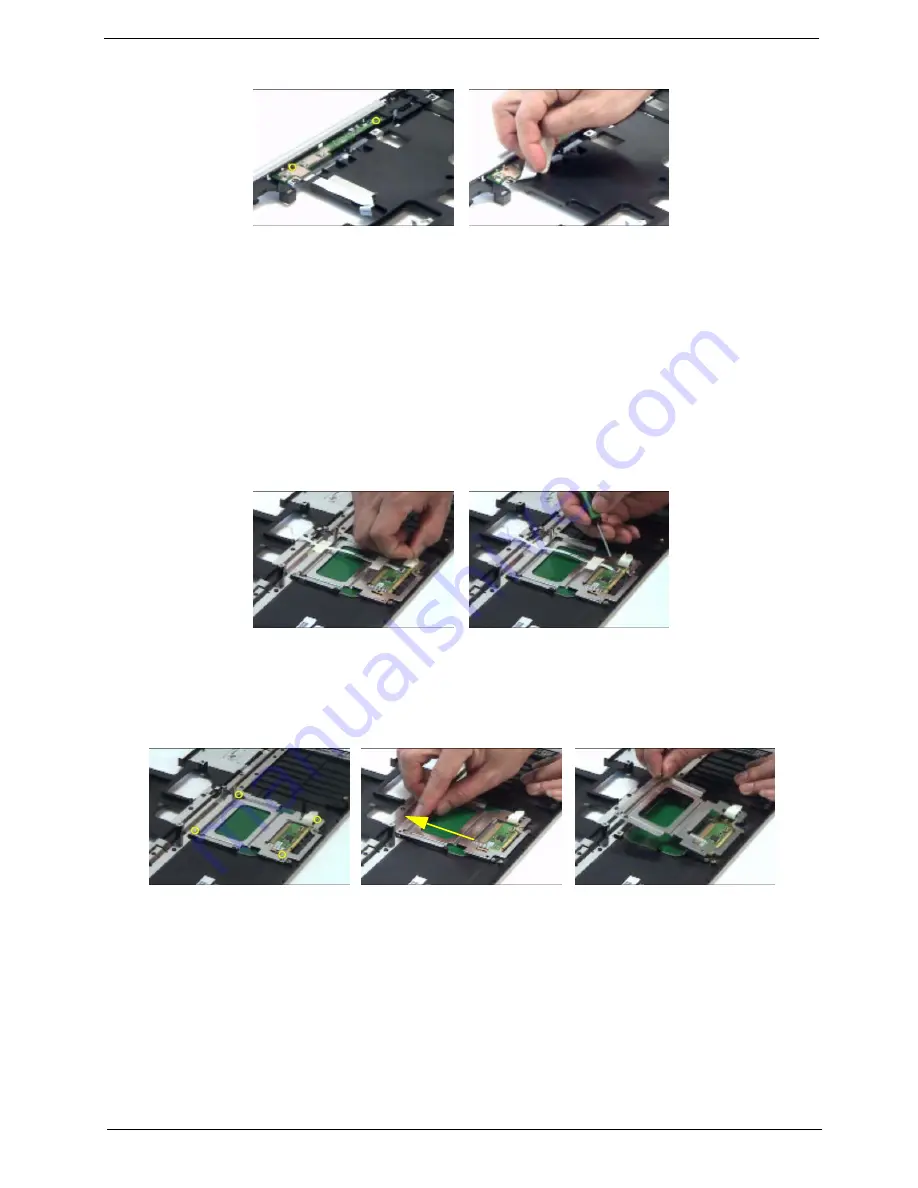
Removing the Touchpad Bracket, the Touchpad Board and the Touchpad

1.

See “Removing the Battery” on page 56.

2.

See “Removing the Middle Cover” on page 60.

3.

See “Removing the Keyboard” on page 60.

4.

See “Removing the Power Board” on page 65.

5.

See “Removing the Upper Case Assembly” on page 65.

6.

Pull back the tape covering the touchpad FFC.

7.

Disconnect the touchpad FFC the remove it.

8.

Remove the four screws securing the touchpad bracket.

9.

Slide the touchpad bracket back as shown.

10.

Then remove the touchpad bracket.

11.

Use a flat headed screw driver to detach the touchpad board.

12.

Then detach the touchpad carefully.

Summary of Contents for TRAVELMATE TravelMate 4080

Page 1: ...TravelMate 4070 4080 Series Service Guide PRINTED IN TAIWAN Service guide files and updates are available on the ACER CSD web for more information please refer to http csd acer com tw ...

Page 2: ...II Revision History Please refer to the table below for the updates made on TravelMate 4070 4080 service guide Date Chapter Updates ...

Page 3: ...pect to the contents hereof and specifically disclaims any warranties of merchantability or fitness for any particular purpose Any Acer Incorporated software described in this manual is sold or licensed as is Should the programs prove defective following their purchase the buyer and not Acer Incorporated its distributor or its dealer assumes the entire cost of all necessary servicing repair and an...

Page 4: ... bits and pieces of additional information related to the current topic WARNING Alerts you to any damage that might result from doing or not doing specific actions CAUTION Gives precautionary measures to avoid possible hardware or software problems IMPORTANT Reminds you to do specific actions relevant to the accomplishment of procedures ...

Page 5: ... NOT be covered in this generic service guide In such cases please contact your regional offices or the responsible personnel channel to provide you with further technical details 2 Please note WHEN ORDERING FRU PARTS that you should check the most up to date information available on your regional web or channel If for whatever reason a part number change is made it will not be noted in the printe...

Page 6: ...double layer Display and graphics T Color Thin Film Transistor TFT LCD displaying at 15 XGA 1024 X 768 15 4 WXGA 1280 X 800 supporting simultaneous multi window viewing on dual displays via Acer GridVistaTM T Intel 915GM integrated 3D graphics featuring Intel Graphics Media Accelerator 950 and up to 128 MB of shared memory supporting Microsoft DirectX 9 0 and dual independent display T Intel 915PM...

Page 7: ...ouchpad with 4 way integrated scroll button T Four easy launch buttons T Two front panel buttons wireless LED button and Bluetooth LED button I O interface T Three USB 2 0 ports T PC Card slot one Type II T External display VGA port T Microphone in jack T Headphone speaker line out jack T Ethernet RJ 45 port T Modem RJ 11 port T DC in jack for AC adaptor Environment T Temperature T Operating 5 C t...

Page 8: ...Chapter 1 3 System Block Diagram ...

Page 9: ...4 TravelMate 4070 4080 Board Layout Top View ...

Page 10: ...MCIA Connector 11 CN9 MDC Connector 12 CN11 Internal Speaker Connector 13 CN13 Power Jack 14 CN12 CRT Connector 15 CN14 Battery Connector 16 CN15 Optical Disk Drive Connector 17 CN17 RJ45 RJ11 Connector 18 CN26 Wireless LAN Controller 19 U11 North Bridge 20 U13 CPU Socket 21 CN20 USB Connector 22 CN21 USB Connector 23 U19 BIOS ROM 24 U4 EC PC97551 Power and I O Connector 25 CN22 RTC Battery 26 CN1...

Page 11: ...CMCIA Connector 31 CN25 HDD Connector 32 CN27 USB Connector 33 CN28 Line out SPEDIF Jack 34 CN29 Microphone Jack 35 CN30 Line in Jack 36 SW3 WLAN Button 37 SW2 Bluetooth Button 38 LED2 Charger LED 39 LED1 Power LED 40 U22 Audio Codec 41 U10 Fan Connector ...

Page 12: ...area for your hands when you use the computer 5 Click buttons Left center and right The left and right buttons function like the left and right mouse buttons the center button serves as a 4 way scroll button 6 Touchpad Touch sensitive pointing device which functions like a computer mouse 7 Status indicators LEDs Light Emitting Diodes that turn on and off to show the status of the computer and its ...

Page 13: ...ates the status of Bluetooth communication optional 5 Wireless communication button indicator Press to enable disable the wireless function Indicates the status of wireless LAN communication optional 6 Line in jack Accepts audio line in devices e g audio CD player stereo walkman 7 Microphone jack Accepts inputs from external microphones 8 Speaker Line Out Headphone jack Connects to audio line out ...

Page 14: ...Emergency eject hole Ejects the optical drive tray when the computer is turned off Icon Item Port Description 1 PC Card slot eject button Ejects the PC Card from the slot 2 PC card slot Accepts one Type II CardBus PC Card 3 Two USB 2 0 ports Connects to Universal Serial Bus USB 2 0 devices e g USB mouse USB camera 4 Network jack Connects to an Ethernet 10 100 based network 5 Modem jack Connects to...

Page 15: ...compatible computer security lock Item Description 1 Hard disc bay Houses the computer s hard disc secured by a screw 2 Battery release latch Unlatches the battery to remove the battery pack 3 Battery bay Houses the computer s battery pack 4 Battery lock Locks the battery in place 5 Cooling fan Helps keep the computer cool Note Do not cover or obstruct the opening of the fan 6 Memory comparment Ho...

Page 16: ...green when in AC mode Icon Function Description Caps Lock Lights when Caps Lock is activated Num Lock Lights when Numeric Lock is activated Media activity Indicates when the hard disk or optical drive is active Power Lights when the computer is on Battery Lights when the battery is being charged Bluetooth Indicates the status of Bluetooth communication Wireless LAN Indicates the status of Bluetoot...

Page 17: ... but can be reset by users To set the Web browser mail and programmable keys run the Acer Launch Manager Launch key Default application P User programmable Acer eManager user programmable Web browser Internet browser user programmable Mail Email application user programmable Hot Key Icon Function Description Fn F1 Fn F2 Acer eManager on page 23 Fn F3 Acer eManager on page 23 Fn F4 ion Description ...

Page 18: ...hen is on all alphabetic characters typed are in uppercase Num Lock Fn F11 When is on the embedded keypad is in numeric mode The keys function as a calculator complete with the arithmetic operators and Use this mode when you need to do a lot of numeric data entry A better solution would be to connect an external keypad Scroll Lock Fn F12 When is on the screen moves one line up or down when you pre...

Page 19: ...rm shortcut functions Below are a few examples Tab Activates the next Taskbar button E Opens the My Computer window F1 Opens Help and Support F Opens the Find All Files dialog box R Opens the Run dialog box M Minimizes all windows shift M Undoes the minimize all windows Application key This key has the same effect as clicking the right mouse button it opens the application s context menu Hot Key I...

Page 20: ...screen external monitor if connected and both the display screen and external monitor Fn q Screen blank Turns the display screen backlight off to save power Press any key to return Fn r Touchpad Toggle Turns the internal touchpad on and off Fn s Speaker toggle Turns the speakers on and off Fn w Volume up Increases the sound volume Fn y Volume down Decreases the sound volume Fn x Brightness up Incr...

Page 21: ...both method NOTE Some fonts and software do not support the Euro symbol Please refer to www microsoft com typography faq faq12 htm for more information The US dollar sign 1 Open a text editor or word processor 2 Either directly press the Euro key at the bottom right of the keyboard for Chinese keyboard or hold Shift and then press the 4 key at the upper center of the keyboard symbol at the upper c...

Page 22: ...utton to scroll up or down and move left or right a page This button mimics your cursor pressing on the right scroll bar of Windows applications NOTE Keep your fingers dry and clean when using the touchpad Also keep the touchpad dry and clean The touchpad is sensitive to finger movement hence the lighter the touch the better the response Taping harder will not increase the touchpad s responsivenes...

Page 23: ...exibly reliably and completely T Acer eSettings Management accesses system information and adjusts settings easily T Acer eNet Management hooks up to location based networks intelligently T Acer ePower Management extends battery power via versatile usage profiles T Acer ePresentation Management connects to a projector and adjusts display settings conveniently For more information press the key to ...

Page 24: ... cna decrypt any file on your system the file specific password will be used to encrypt files by default or you cna choose to enter your own file specific password when encrypting a file NOTE The password used encrypt a file is the unique key that the system needs to decrypt it If you lose the password the supervisor password is the only other key capable of decrypting the file If you lose both pa...

Page 25: ...stem T Optical drive deivces includes any kind of CD ROM or DVD ROM drives T Floppy disk drives 3 5 inch disks only To activate Acer eLock Management a password must be set first Once set you may apply lock to any of the three kinds of devices Lock s will immediately be set without any reboot necessary and will remain locked after rebooting until unlocked If you do not set a password Acer eLock Ma...

Page 26: ...e performance of your Acer notebook It provides you with the following options to enhance overall system performance T Memory optimization releases unused memory and check usage T Disk optimization removes unneeded items and files T Speed optimization improves the usability and performance of your Windows XP system ...

Page 27: ...in a hidden partition on your system s HDD User created backups are stored on D drive Acer eRecovery Management provides you with T Password protection T Recovery of applications and drivers T Image data backup T Back up to HDD set recovery point T Back up to CD DVD T Image data recovery tools T Recover from a hidden partition factory defaults T Recover from the HDD most recent user defined recove...

Page 28: ... Acer eSettings Management allows you to inspect hardware specifications and to monitor the system health status Furthermore Acer eSettings Management enables you to optimize your Windows operating system so your computer runs faster smoother and better Acer eSettings Management also T Provides a simple graphical user interface for navigating through the program effortlessly T Displays general sys...

Page 29: ...on the Acer eNet Management icon on your netebook or start the program from the Start menu You also have the option to set Acer eNet Management to start automatically when you boot up your PC Acer eNet Management automatically detects the best settings for a new location while offering you the freedom to manually adjust the settings to match your needs simply by right clicking on the icon in the t...

Page 30: ...ing Technology interface or double click the Acer ePower Management icon in the task tray Acer Mode The default setting is Maximum Performance You can adjust CPU speed LCD brightness and other settings or click on buttons to turn the following functions on off Wireless LAN Bluetooth CardBus Memory Card Audio and Wired LAN DC Mode To suit your usage there are four pre defined profiles Entertainment...

Page 31: ...e panel on the lower left hand side of the window You can also click Advanced Settings to T Set alarms T Re load factory defaults T Select what actions will be taken when the cover is closed and set passwords for accessing the system after Hibernation or Standby T View information about Acer ePower Management ...

Page 32: ...Chapter 1 27 Acer ePresentation Management Acer ePresentation Management lets you select from two of the most common projector resolutions XGA and SVGA ...

Page 33: ...ache 1 60 1 73 1 86 2 2 13 2 26 GHz 533 MHz FSB Intel Pentium M 725 processor 2MB L2 Cache 1 60 GHz 400 MHz FSB Intel Celeron M processor 360 370 380 1 MB L2 cache 1 40 1 50 1 60 GHz 400 MHz FSB CPU package Intel socketable 478 pins Micro FCPGA CPU core voltage Low speed 0 8V High speed 1 5V CPU I O voltage 1 2V BIOS Item Specification BIOS vendor Pheonix BIOS BIOS Version BIOS ROM type Flash ROM ...

Page 34: ...pports DIMM voltage 1 8 V 0 9V Supports DIMM package 200 pin so DIMM Memory module combinations You can install memory modules in any combinations as long as they match the above specifications Memory Combinations Slot 1 Slot 2 Total Memory 0MB 256MB 256MB 0MB 512MB 512MB 0MB 1024MB 1024MB 256MB 0MB 256MB 256MB 256MB 512MB 256MB 512MB 768MB 256MB 1024MB 1280MB 512MB 0MB 512MB 512MB 256MB 768MB 512...

Page 35: ...odule for this product Floppy Disk Specifications Media recognition 2DD 720KB 2HD 1 2 MB 3 mode 2HD 1 44MB Sectors track 9 15 18 Tracks 80 80 80 Data transfer rate Kbit s 1 MB 1 6 MB 2 MB Rotational speed RPM 300 360 300 Read write heads 2 Encoding method MFM Power Requirement Input Voltage V 5V Hard Disk Drive Interface Item Vendor Model Name HGST MORAGA IC25N060ATMR04 0 08K0634 Seagate N2 ST9608...

Page 36: ... Drive Mounting Horizontal Vertical Read Write Read Speed Max 24X 3 600 KB sec for CD ROM Max 24X 3 600 KB sec for CD RW Write Speed Max 24X 3 600 KB sec for CD R Max 10X 1 500 KB sec for CD RW Max 24X 3 600 KB sec for US RW CAV 24X CAV 24X P CAV 24X 20X 16X CLV 10X 8X 4X CLV 10X 4X P CAV 24X 16X Mounting Orientation Horizontal Vertical All angles Buffer Under Run 2MB Power consumption DC 5v 1 2A ...

Page 37: ...age DC 5V 5 operation DC 5V 8 start up DVD RW Interface Item Specification Vendor model name TOSHIBA TS L532A Performance Specification Transfer rate KB sec 1 Read DVD ROM DVD R CD ROM 2 Write CD R CD RW HS RW US RW 3 ATAPI Interface PIO mode DMA mode Ultra DMA mode MAX 8X CAV MAX 10800kB s MAX 4X CAV MAX 5400kB s MAX 24X CAV MAX 3600kB s 4X 8X CLV MAX 24X ZCLV 4X CLV 4X 8X 10X CLV 8X 10X CLV MAX ...

Page 38: ...ate Internal microphone Yes Internal speaker Quantity Yes Supports PnP DMA channel DMA channel 0 DMA channel 1 Supports PnP IRQ IRQ10 IRQ11 Video Interface Item Specification Vendor Model Name built in Intel 915GM Video memory size up to 128MB for Aspire 3000 5000 up to 64MB for Aspire 3500 Chip voltage Core 2 5V 1 5V Supports ZV Zoomed Video port NO Graph interface 4X AGP Accelerated Graphic Port...

Page 39: ...e Serial port function control Enable Disable by BIOS Setup PCMCIA Port Item Specification PCMCIA controller TI PCI1510A Supports card type Type II No Tpye III Number of slots One type II Access location Right side Supports ZV Zoomed Video port NO Supports 32 bit CardBus Yes IRQ17 Keyboard Item Specification Keyboard controller KBC NS97551 Keyboard vendor Darfon Total number of keypads 88 89 key W...

Page 40: ... Fall Time msec 16 25 5ms for rise 20 ms for decay Nominal Input Voltage VDD not show not show Typical Power Consumption watt 6 5 max 4 38 for lamp Weight 585 585 Physical Size mm 344 W x222 H x6 5 D 344 W x222 H x6 5 D Support Color Native 262K colours 262K colours Viewing Angle degree Horizontal Right Left Vertial Upper Lower 40 40 10 30 45 45 15 35 Temperature Range C Operating Storage shipping...

Page 41: ...d C22 2 No 950 2 The subject product rated 200 240V 50Hz must comply with low voltage directive 73 23EEC EMI Requirements 1 The subject product rated 100 120V 60Hz must meet the EMI requirements of FCC part 15 Subpart B for Class B Digital Device and get FCC Certification before marketing into USA and Canada 2 The subject product rated 200 240V 50Hz must meet the EMC Directive 89 336 EEC 3 The sub...

Page 42: ...Hz 0 51mm peak to peak 62 6 500Hz 4 0G Mechanical Specification Item Specification Dimensions 364 W x 279 D x 33 9 38 9 H mm 14 3 3X 10 98x 1 33 1 53 inches Weight 6 4 Ibs 2 91kg for 15 XGA LCD model 6 5 lbs 2 94kg for 15 4 WXGA LCD model I O Ports Three USB 2 0 ports Ethernet RJ 45 port Modem RJ 11 port External display VGA port Microphone in jack Line in jack Headphones speaker line out jack Typ...

Page 43: ...ant to change boot device without entering BIOS Setup Utility please set the parameter to enabled Press F12 during POST to enter multi boot menu In this menu user can change boot device without entering BIOS SETUP Utility PhoenixBIOS Setup Utility CPU Type Intel R Pentium R processor 1 73GHz CPU Speed System BIOS Version 2A02 VGA BIOS Version Alviso 1219 KBC Version 1A16 Serial Number LXT123456705...

Page 44: ...d this item T Press while you are in any of the menu options to go to the Exit menu T In any menu you can load default settings by pressing t You can also press u to save any changes made and exit the BIOS Setup Utility NOTE You can change the value of a parameter if it is enclosed in square brackets Navigation keys for a particular menu are shown on the bottom of the screen Help for parameters ar...

Page 45: ...n of this system ATAPI Serial Number This field shows the serial number of devices installed on secondary IDE master Serial Number This field displays the serial number of this unit Asset Tag Number An Asset Tag with 32 bytes will be stored in EEPROM Default value is set as 0000000000000000 in binary code PhoenixBIOS Setup Utility CPU Type Intel R Pentium R processor 1 73GHz CPU Speed System BIOS ...

Page 46: ... computing object identifiers OIDs It uses the serial number in the local Ethernet card combined with the date and time to generate a 128 bit 16bytes number For Acer product this field displays UUID number A UUID string will be stored in the secured data area which is an alphanumeric string of maxium 16 bytes in length Parameter Description ...

Page 47: ...nformation Main Security Boot Exit Item Specific Help System Time 05 45 48 System Date 08 30 2005 System Memory 640 KB Extended Memory 1040 MB Video Memory 128MB Quiet Boot Enabled Power On Display Both Network Boot Enabled F12 Boot Menu Disabled Tab Shift Tab or Enter selects field F1 Help Select Item F5 F6 Change Values F9 Setup Defaults Esc Exit Select Menu Enter Select 4Sub Menu F10 Save and E...

Page 48: ...es if Customer Logo will be displayed or not shows Summary Screen is disabled or enabled Enabled Customer Logo is displayed and Summary Screen is disabled Disabled Customer Logo is not displayed and Summary Screen is enabled Option Enabled or Disabled Power on display Auto During power process the system will detect if any display device is connected on external video port If any external display ...

Page 49: ...ssword Is Clear Set Supervisor Password Set User Password Set HDD Password Password on Boot Disabled Supervisor Password controls accesses of the whole setup utility It can be used to boot up when Password on boot is enabled F1 Help Select Item F5 F6 Change Values F9 Setup Defaults Esc Exit Select Menu Enter Select 4 Sub Menu F10 Save and Exit Enter Enter Enter Exit Security HDD Password Is Clear ...

Page 50: ...nabled Clear or Set HDD Password Is Shows the setting of the HDD password Clear or Set Set User Password Press Enter to set the user password When user password is set this password protects the BIOS Setup Utility from unauthorized access The user can enter Setup menu only and does not have right to change the value of parameters Set Supervisor Password Press Enter to set the supervisor password W...

Page 51: ...OS Setup Utility Removing a Password Follow these steps 1 Use the w and y keys to highlight the Set Supervisor Password parameter and press the e key The Set Password box appears 2 Type the current password in the Enter Current Password field and press e 3 Press e twice without typing anything in the Enter New Password and Confirm New Password fields The computer then sets the Supervisor Password ...

Page 52: ... on boot parameter 6 When you are done press u to save the changes and exit the BIOS Setup Utility If the verification is OK the screen will display as following The password setting is complete after the user presses u If the current password entered does not match the actual current password the screen will show you the Setup Warning If the new password and confirm new password strings do not ma...

Page 53: ...ixBIOS Setup Utility Info Main Advanced Security Exit Item Specific Help Floppy Devices Hard Drive and indicate device categories Use Enter to expand collapses Boot order is top down using only the top device in each category Use F6 and F5 to move highlighted item up and down F1 Help Select Item F5 F6 Change Values F9 Setup Defaults Esc Exit Select Menu Enter Select 4 Sub Menu F10 Save and Exit Ne...

Page 54: ...etup data to CMOS Load Setup Default Load default values for all SETUP item Discard Changes Load previous values from CMOS for all SETUP items Save Changes Save Setup Data to CMOS PhoenixBIOS Setup Utility Info Main Advanced Security Boot Item Specific Help Exit Saving Changes Exit Dicarding Changes Load Setup Defaults Exit System Setup and save your changes to CMOS F1 Help Select Item F5 F6 Chang...

Page 55: ...cause the BIOS is not completely loaded Create Crisis Recovery Diskette 1 Rename BIOS file of this product to BIOS wph 2 Copy BIOS wph file to crisis folder and overwrite the original BIOS wph file 3 Insert a blank floppy diskette to floppy drive 4 Run cs bat and follow its instructions to create crisis recovery diskette Recover BIOS from Crisis Recovery Diskette 1 Insert the crisis recovery diske...

Page 56: ...51 Chapter 2 ...

Page 57: ...trap and conductive mat for preventing electrostatic discharge T Flat bladed screw driver T Phillips screw driver T Tweezers T Plastic Flat bladed screw driver T Hexed Screw Driver NOTE The screws for the different components vary in size During the disassembly process group the screws with the corresponding components to avoid mismatch when putting back the components Chapter 3 Machine Disassembl...

Page 58: ... the following 1 Turn off the power to the system and all peripherals 2 Unplug the AC adapter and all power and signal cables from the system NOTE Aspire 9100 series product uses mylar or tape to fasten the FFC FPC connectors cable you may need to tear the tape or mylar before you disconnect different FFC FPC connectors ...

Page 59: ...ery HDD Module Hinge Caps HDD LCD Module 6 Keyboard Lower Case Assembly 3 3 11 4 Dimm Cover Memory 2 2 Launch Board Modem Cover Modem Board 1 2 CPU RTC Battery Mini PCI Card Plate Thermal Module 4 3 HDD Holder 2 2 Middle Cover Upper Case Assembly Wireless LAN Antenna Touchpad Cover Touchpad Button Pad Touchpad Upper Case Touchpad Cable Touchpad Scroll Key FDD Module VGA Heatsink Plate CPU Heatsink...

Page 60: ...5X IO R00 B SCREW M2 0X0 4P 3FP ZK NL C SCREW M2 5 K 5 2 X0 85 4 ZK NL D SCREW M2 5X0 45 10K NIL E SCREW M2 5X0 45 8K ZBL F SCREW M2 5X0 45P 3F NI G SCREW M3 0X0 8P 3K NL 4 LCD Cushions 4 LCD Bezel Inverter LCD 4 LCD Panel LCD Brackets LCD Coaxial Cable 4 1 LCD Module ...

Page 61: ...Chapter 3 56 Removing the Battery 1 Unlatch the battery latch then remove the battery ...

Page 62: ...w securing the hard disk drive HDD cover 3 Then remove the HDD cover 4 Pull the HDD module backwards as shown 5 Remove the HDD module Disassembling the Hard Disc Drive Module 1 Remove two screw securing the HDD bracket 2 Remove the other two screw on the other side 3 Take out the HDD from the HDD bracket ...

Page 63: ...e Hard Disc Drive Module on page 57 3 Remove the screw securing the optical disc drove ODD module 4 Push the ODD module outwards with a flat headed screw driver 5 Then remove the ODD module Disassembling the Optical Disc Drive Module 1 Remove two screws securing the ODD bracket 2 Then remove the ODD bracket ...

Page 64: ...apter 3 Removing the Memory 1 See Removing the Battery on page 56 2 Remove the two screws securing the DIMM cover then remove the DIMM cover 3 Pop out the memory 4 Then remove the memory from the DIMM socket ...

Page 65: ...ing the Middle Cover on page 60 3 Remove the four screws securing the keyboard 4 Turn the keyboard over as shown 5 Disconnect the keyboard cable then remove the keyboard Removing the Fan the CPU Thermal Module and the CPU 1 See Removing the Battery on page 56 2 See Removing the Middle Cover on page 60 3 See Removing the Keyboard on page 60 4 Remove the three screws securing the system fan 5 Discon...

Page 66: ...U lock with a flat headed screw driver 10 Then detch the CPU from the socket carefully Removing the Wireless LAN Card 1 See Removing the Battery on page 56 2 See Removing the Middle Cover on page 60 3 Pop out the wireless LAN card 4 Disconnect the main and the auxiliary antennae 5 Then remove the wireless LAN card from the main unit Removing the LCD Module 1 See Removing the Battery on page 56 2 S...

Page 67: ...ape securing the wireless LAN antennae then release the antennae 7 Remove the two screws securing the LCD module on the rear side 8 Remove the two screws securing the LCD module on the bottom 9 Then detach the LCD module carefully ...

Page 68: ...e 61 7 Detach the two rubber pads and the two screw pads 8 Remove the four screws securing the LCD bezel 9 Detach the LCD bezel carefully 10 Remove the nine screws securing the LCD to the LCD panel 11 Take out the LCD assembly from the LCD panel 12 Disconnect the LCD inverter cable 13 Discnnect the LCD inverter board 14 Turn over the LCD 15 Disconnect the LCD cable 16 Remove the four screws securi...

Page 69: ...Chapter 3 64 ...

Page 70: ...er case assembly on the bottom 7 Remove the three screws securing the upper case assembly 8 Disconnect the touchpad cable 9 Disconnect the power board cable 10 Then detach the upper case assembly Removing the Power Board 1 See Removing the Battery on page 56 2 See Removing the Hard Disc Drive Module on page 57 3 See Removing the Optical Disc Drive Module on page 58 4 See Removing the Memory on pag...

Page 71: ...moving the Power Board on page 65 5 See Removing the Upper Case Assembly on page 65 6 Pull back the tape covering the touchpad FFC 7 Disconnect the touchpad FFC the remove it 8 Remove the four screws securing the touchpad bracket 9 Slide the touchpad bracket back as shown 10 Then remove the touchpad bracket 11 Use a flat headed screw driver to detach the touchpad board 12 Then detach the touchpad ...

Page 72: ... the CIR receiver cable 8 Then disconnect the audio board FFC cable 9 Disconnect the speaker set cable 10 Then detach the speaker set from the lower case Removing the SW DJ Board Assembly 1 See Removing the Battery on page 56 2 See Removing the Middle Cover on page 60 3 See Removing the Keyboard on page 60 4 See Removing the Power Board on page 65 5 See Removing the Upper Case Assembly on page 65 ...

Page 73: ...e Keyboard on page 60 4 See Removing the Power Board on page 65 5 See Removing the Upper Case Assembly on page 65 6 See Removing the Speaker Set on page 67 7 See Removing the SW DJ Board Assembly on page 67 8 Remove the screw securing the audio board 9 Detach the audio board FFC 10 Release the CIR receiver cable 11 Then detach the audio board Removing the VGA Thermal Module 1 See Removing the Batt...

Page 74: ...uring the modem board 7 Disconnect the modem board connector 8 Disconnect the modem board cable then remove the board Removing the Main Board 1 See Removing the Battery on page 56 2 See Removing the Middle Cover on page 60 3 See Removing the Keyboard on page 60 4 See Removing the Power Board on page 65 5 See Removing the Upper Case Assembly on page 65 6 See Removing the Speaker Set on page 67 7 Se...

Page 75: ...oard on page 60 4 See Removing the Power Board on page 65 5 See Removing the Upper Case Assembly on page 65 6 See Removing the Speaker Set on page 67 7 See Removing the SW DJ Board Assembly on page 67 8 See Removing the Audio Board on page 68 9 See Removing the VGA Thermal Module on page 68 10 See Removing the Modem Board on page 69 11 See Removing the Main Board on page 69 12 Turn over the main b...

Page 76: ...71 Chapter 3 ...

Page 77: ... which page to go to Symptoms Verified Go To Power failure The power indicator does not go on or stay on Power System Check on page 74 POST does not complete No beep or error codes are indicated Power On Self Test POST Error Message on page 77 Undetermined Problems on page 89 POST detects an error and displayed messages on screen Error Message List on page 78 Other symptoms i e LCD display problem...

Page 78: ...the drive to fail Do the following to select the test device 1 Boot from the diagnostics diskette and start the diagnostics program 2 See if CD ROM Test is passed when the program runs to CD ROM Test 3 Follow the instructions in the message window If an error occurs reconnect the connector on the System board If the error still remains 1 Reconnect the external diskette drive CD ROM module 2 Replac...

Page 79: ...IMM is fully installed into the connector A loose connection can cause an error Power System Check To verify the symptom of the problem power on the computer using each of the following power sources 1 Remove the battery pack 2 Connect the power adapter and check that power is supplied 3 Disconnect the power adapter and install the charged battery pack then check that power is supplied by the batt...

Page 80: ...e following T Replace the System board T If the problem is not corrected see Undetermined Problems on page 89 T If the voltage is not correct go to the next step NOTE An audible noise from the power adapter does not always indicate a defect 3 If the power on indicator does not light up check the power cord of the power adapter for correct continuity and installation 4 If the operational charge doe...

Page 81: ... that has less than 50 of the total power remaining when installed in the computer If the battery status indicator does not light up remove the battery pack and let it return to room temperature Re install the battery pack If the charge indicator still does not light up replace the battery pack If the charge indicator still does not light up replace the DC DC charger board Touchpad Check If the to...

Page 82: ...ext possible FRU to be replaced when servicing a computer If the symptom is not listed see Undetermined Problems on page 89 The following lists the error messages that the BIOS displays on the screen and the error symptoms classified by function NOTE Most of the error messages occur during POST Some of them display information about a hardware device e g the amount of memory installed Others may i...

Page 83: ...ault Settings in BIOS Setup Utility Hard disk drive System board Stuck Key see Keyboard or Auxiliary Input Device Check on page 73 Keyboard error see Keyboard or Auxiliary Input Device Check on page 73 Keyboard Controller Failed see Keyboard or Auxiliary Input Device Check on page 73 Keyboard locked Unlock key switch Unlock external keyboard Monitor type does not match CMOS Run Setup Run Load Defa...

Page 84: ... Setup Utility System cache error Cache disabled System board CPU ID System board DMA Test Failed DIMM System board Software NMI Failed DIMM System board Fail Safe Timer NMI Failed DIMM System board Device Address Conflict Run Load Default Settings in BIOS Setup Utility RTC battery System board Allocation Error for device Run Load Default Settings in BIOS Setup Utility RTC battery System board Fai...

Page 85: ...source battery pack and power adapter See Power System Check on page 74 Reconnect the LCD connector Hard disk drive LCD inverter ID LCD cable LCD Inverter LCD System board No beep power on indicator turns on and LCD is blank But you can see POST on an external CRT Reconnect the LCD connectors LCD inverter ID LCD cable LCD inverter LCD System board No beep power on indicator turns on and a blinking...

Page 86: ...ze 18h 8254 timer initialization 1Ah 8237 DMA controller initialization 1Ch Reset Programmable Interrupt Controller 20h 1 3 1 1 Test DRAM refresh 22h 1 3 1 3 Test 8742 Keyboard Controller 24h Set ES segment register to 4 GB 26h Enable A20 line 28h Autosize DRAM 29h Initialize POST Memory Manager 2Ah Clear 215 KB base RAM 2Ch 1 3 4 1 RAM failure on address line xxxx 2Eh 1 3 4 3 RAM failure on data ...

Page 87: ...Setup System Management Mode SMM area 6Ah Display external L2 cache size 6Bh Load custom defaults optional 6Ch Display shadow area message 6Eh Display possible high address for UMB recovery 70h Display error messages 72h Check for configuration errors 76h Check for keyboard errors 7Ch Set up hardware interrupt vectors 7Eh Initialize coprocessor if present 80h Disable onboard Super I O ports and IR...

Page 88: ...ematic rate A8h Erase F2 prompt AAh Scan for F2 key stroke ACh Enter SETUP AEh Clear Boot flag B0h Check for errors B2h POST done prepare to boot operating system B4h 1 One short beep before boot B5h Terminate QuietBoot optional B6h Check password optional B9h Prepare Boot BAh Initialize DMI parameters BBh Initialize PnP Option ROMs BCh Clear parity checkers BDh Display MultiBoot menu BEh Clear sc...

Page 89: ...h Set Huge Segment E9h Initialize Multi Processor EAh Initialize OEM special code EBh Initialize PIC and DMA ECh Initialize Memory type EDh Initialize Memory size EEh Shadow Boot Block EFh System memory test F0h Initialize interrupt vectors F1h Initialize Run Time Clock F2h Initialize video F3h Initialize System Management Mode F4h 1 Output one beep before boot F5h Boot to Mini DOS F6h Clear Huge ...

Page 90: ...cable LCD System board Indicator Related Symptoms Symptom Error Action in Sequence Indicator incorrectly remains off or on but system runs correctly Reconnect the inverter board Inverter board System board Power Related Symptoms Symptom Error Action in Sequence Power shuts down during operation Power source battery pack and power adapter See Power System Check on page 74 Battery pack Power adapter...

Page 91: ...hibernation Keyboard if control is from the keyboard Hard disk drive System board The system doesn t enter hibernation mode and four short beeps every minute See S4 Sleeping State on page 36 Press Fn oand see if the computer enters hibernation mode Touchpad Keyboard Hard disk connection board Hard disk drive System board The system doesn t enter standby mode after closing the LCD See S4 Sleeping S...

Page 92: ... Ensure the Parallel Port in the Onboard Devices Configuration of BIOS Setup Utility is set to Enabled Onboard Devices Configuration Run printer self test Printer driver Printer cable Printer System Board Serial or parallel port device problems Ensure the Serial Port in the Devices Configuration of BIOS Setup Utility is set to Enabled Device driver Device cable Device System board Keyboard Touchpa...

Page 93: ... discharge or software errors FRU replacement should be considered only when a recurring problem exists When analyzing an intermittent problem do the following 1 Run the advanced diagnostic test for the system board in loop mode at least 10 times 2 If no error is detected do not replace any FRU 3 If any error is detected replace the FRU Rerun the test to verify that there are no more errors ...

Page 94: ...operating correctly See Power System Check on page 74 1 Power off the computer 2 Visually check them for damage If any problems are found replace the FRU 3 Remove or disconnect all of the following devices T Non Acer devices T Printer mouse and other external devices T Battery pack T Hard disk drive T DIMM T CD ROM Diskette drive Module T PC Cards 4 Power on the computer 5 Determine if the problem...

Page 95: ...Chapter 5 90 Top View Jumper and Connector Locations Chapter 5 ...

Page 96: ...MCIA Connector 11 CN9 MDC Connector 12 CN11 Internal Speaker Connector 13 CN13 Power Jack 14 CN12 CRT Connector 15 CN14 Battery Connector 16 CN15 Optical Disk Drive Connector 17 CN17 RJ45 RJ11 Connector 18 CN26 Wireless LAN Controller 19 U11 North Bridge 20 U13 CPU Socket 21 CN20 USB Connector 22 CN21 USB Connector 23 U19 BIOS ROM 24 U4 EC PC97551 Power and I O Connector 25 CN22 RTC Battery 26 CN1...

Page 97: ... Connector 31 CN25 HDD Connector 32 CN27 USB Connector 33 CN28 Line out SPEDIF Jack 34 CN29 Microphone Jack 35 CN30 Line in Jack 36 SW3 WLAN Button 37 SW2 Bluetooth Button 38 LED2 Charger LED 39 LED1 Power LED 40 U22 Audio Codec 41 U10 Fan Connector ...

Page 98: ...93 Chapter 5 ...

Page 99: ... is made it will not be noted on the printed Service Guide For ACER AUTHORIZED SERVICE PROVIDERS your Acer office may have a DIFFERENT part number code from those given in the FRU list of this printed Service Guide You MUST use the local FRU list provided by your regional Acer office to order FRU parts for repair and service of customer machines NOTE To scrap or to return the defective parts you s...

Page 100: ...80 Exploded Diagram TravelMate 4070 4080 FRU List Adapter NS ADP 19V 3 42A PA 1650 02QR 90 264V LF AP 06503 010 NS ADP 19V 3 42A SLS0335A19A57LF 90 264V EU AP 06506 002 NS ADP 19V 3 42A SADP 65KB DBHF 90 264V LF AP 06501 009 Battery ...

Page 101: ...LO PACK LI ION 4S1P 2 0A BT 00407 001 BATTERY SANYO PACK LI ION 4S1P 2 0A BT 00403 004 BATTERY SONY PACK LI ION 4S1P 1 96A BT 00404 004 Board NS MODEM 56K MDC T60M845 02 EU 54 TAKV7 001 NS BLUETOOTH MODULE W ANTENNA 54 T48V7 001 NS W L 802 11B G WM3B2200BGMW2 KI CAX01 008 NS LAUNCH BOARD 55 TAKV7 001 NS TOUCH PAD BOARD 55 TAKV7 002 Cable NS FFC CABLE TP B TO MB 50 T50V7 001 TravelMate 4070 4080 FR...

Page 102: ...3V7 007 POWER CORD AU 3 PIN 27 A03V7 008 POWER CORD DANISH 3 PIN 27 A03V7 006 POWER CORD AF 3 PIN 27 T48V7 001 Case Cover Bracket Assembly 5 MIDDEL COVER ERGO W BUTTON LIGHT GREEN SILVER 42 T50V7 101 6 UPPER CASE W TOUCHPAD BRACKET MIC BLUETOOTH CABLE 60 T91V7 001 UPPER CASE W TOUCHPAD BRACKET MIC W O BLUETOOTH CABLE 60 T91V7 002 11 LOWER CASE W SPEAKER 60 A51V7 002 13 DIMM WIRELESS COVER 42 A50V7...

Page 103: ...LE SEMPRON 2800 25WD KC S2802 25D AMD MOBILE SEMPRON 3000 25WD KC S3002 25D AMD MOBILE TURION 64 ML28 KC TML02 280 AMD MOBILE TURION 64 ML30 KC TML02 300 AMD MOBILE TURION 64 ML32 KC TML02 320 AMD MOBILE TURION 64 ML34 KC TML02 340 AMD MOBILE TURION 64 ML37 KC TML02 370 Optical Disk Drive Module NS DVD CDRW COMBO MODULE 24X PHILIPS SCB5265 LF 6M A65V7 004 TravelMate 4070 4080 FRU List ...

Page 104: ...001 DVD CDRW COMBO LITE ON SOSC 2483K LF GB KO 02409 011 OPTICAL DEVICE HOLDER FIX 42 T51V7 003 DVD CDRW BEZEL FOR G BASE 42 A65V7 003 DVD CDRW COMBO MODULE HLDS GCC 4244N LF 6M ATKV7 002 DVD CDRW COMBO HLDS GCC 4244N GB LF KO 0240A 004 OPTICAL DEVICE HOLDER FIX 42 T51V7 003 DVD DUAL BEZEL G BASE 42 A65V7 003 DVD DUAL MODULE PANASONIC UJ 840BAA2 G BASE 6M A51V7 003 DVD DUAL DRIVE PANASONIC UJ 840B...

Page 105: ...ve NS 40G SEAGATE 2 5 IN 4200RPM N2 1ST9402113A ROHS F W 3 01 KH 04001 016 40G TOSHIBA 2 5 IN 4200RPM PLUTO MK4025GAS ROHS F W KA100A KH 04004 005 40G HGST 2 5 IN 4200RPM HAKONA A F W A70G KH 04007 013 40G WD 2 5 IN 5400RPM ML40 WD400UE 22HCT0 ROHS KH 04008 025 40G SAMSUNG 2 5 IN 5400RPM M40MP0402H ROHS F W YQ200 04 KH 0400B 003 60G SEAGATE 2 5 IN 4200RPM N2 2ST960812A F W 3 04 KH 06001 003 60G TO...

Page 106: ...RD DARFON Korea KB A2707 006 AS1680 AS1410 KEYBOARD DARFON UK KB A2707 007 AS1680 AS1410 KEYBOARD DARFON German KB A2707 008 AS1680 AS1410 KEYBOARD DARFON Italian KB A2707 009 AS1680 AS1410 KEYBOARD DARFON French KB A2707 010 AS1680 AS1410 KEYBOARD DARFON Swiss G KB A2707 011 AS1680 AS1410 KEYBOARD DARFON Portuguese KB A2707 012 AS1680 AS1410 KEYBOARD DARFON Arabic KB A2707 013 AS1680 AS1410 KEYBO...

Page 107: ...AS1680 AS1410 KEYBOARD DARFON Hebrew KB A2707 024 AS1680 AS1410 KEYBOARD DARFON Russian KB A2707 025 LCD Module NS LCD 15 0 IN MODULE SAMSUNG LTN150XB L03 V LF 6M ATKV7 011 NS LCD 15 0 IN XGA SAMSUNG LTN150XB L03 V LF LK 15006 008 NS LCD INVERTER BOARD 19 TAKV7 001 NS LCD CABLE 15 IN XGA 50 T50V7 004 NS LCD BRACKET W HINGE 15 IN L 33 T50V7 002 TravelMate 4070 4080 FRU List ...

Page 108: ... LCD BRACKET W HINGE 15 IN R 33 T50V7 003 NS LCD PANEL W LOGO ANTENNA 14 15 IN 60 T50V7 102 NS LCD BEZEL W RUBBER PAD 15 IN 60 T50V7 004 LCD 15 0 IN MODULE LPL LP150X07 TLA2 LF 6M ATKV7 013 LCD 15 0 IN XGA LPL LP150X07 TLA2 LF LK 15008 019 NS LCD INVERTER BOARD 19 TAKV7 001 NS LCD CABLE 15 IN XGA 50 T50V7 004 NS LCD BRACKET W HINGE 15 IN L 33 T50V7 002 NS LCD BRACKET W HINGE 15 IN R 33 T50V7 003 N...

Page 109: ...W RUBBER PAD 15 4 IN 60 T50V7 006 LCD 15 4 MODULE SAMSUNG LTN154X3 L01 V104 6M ATKV7 014 LCD 15 4 WXGA SAMSUNG LTN154X3 L01 V104 LK 15406 009 LCD INVERTER BOARD 19 TAKV7 001 LCD CABLE 15 4 IN WXGA 50 T50V7 006 LCD BRACKET W HINGE 15 4 IN L 33 T50V7 004 LCD BRACKET W HINGE 15 4 IN R 33 T50V7 005 LCD PANEL W LOGO ANTENNA 15 4 IN 60 T50V7 103 LCD BEZEL W RUBBER PAD 15 4 IN 60 T50V7 006 LCD 15 4 MODUL...

Page 110: ...W RUBBER PAD 15 IN 60 T50V7 004 LCD 15 0 IN MODULE CMO N150X3 L07 LF W O WIRELESS 6M ATKV7 022 LCD 15 0 IN XGA CMO N150X3 L07 REV C4 LF LK 1500D 012 LCD INVERTER BOARD 19 TAKV7 001 LCD CABLE 15 IN XGA 50 T50V7 004 LCD BRACKET W HINGE 15 IN L 33 T50V7 002 LCD BRACKET W HINGE 15 IN R 33 T50V7 003 LCD PANEL W LOGO W O ANTENNA 14 15 IN 60 A56V7 102 LCD BEZEL W RUBBER PAD 15 IN 60 T50V7 004 LCD 15 0 IN...

Page 111: ...CD BRACKET W HINGE 15 4 IN L 33 T50V7 004 LCD BRACKET W HINGE 15 4 IN R 33 T50V7 005 LCD PANEL W LOGO ANTENNA 15 4 IN 60 T56V7 103 LCD BEZEL W RUBBER PAD 15 4 IN 60 T50V7 006 Main Board NS MAINBOARD 915GM UMA W PCMCIA W O CPU MEMORY LB TAK02 001 Memory NS MEMORY DDR333 256MB INFINEON HYS64D32020HDL 6 C 11u KN 25602 012 MEMORY DDR333 256MB NANYA NT256D64SH8C0GM 6K KN 25603 019 MEMORY DDR333 256MB S...

Page 112: ... Screw NS SCREW M2 0X3 0 I NI NYLOK 86 A03V7 012 NS SCREW I2 5 3M BNIH M2 5L3 86 T25V7 012 NS SCREW M2 5 4L BZN NYLOK 86 A03V7 006 NS SCREW M2 0X5 I NI NYLOK 86 T23V7 006 NS SCREW MM25060IL69 86 A08V7 004 NS SCREW M2 0 5 I NI NYLOK 86 T23V7 010 NS SCREW M2 0X2 5 I NI NYLOK 86 A03V7 007 NS SCREW I2 3M NIHY M2L3 86 T25V7 008 NS SCREW M1 7 3 0 I BK 86 T50V7 001 NS SCREW I3 3 5M NIH M3L3 5 86 A03V7 01...

Page 113: ...Chapter 6 108 ...

Reviews: