background image

14

Chapter 1

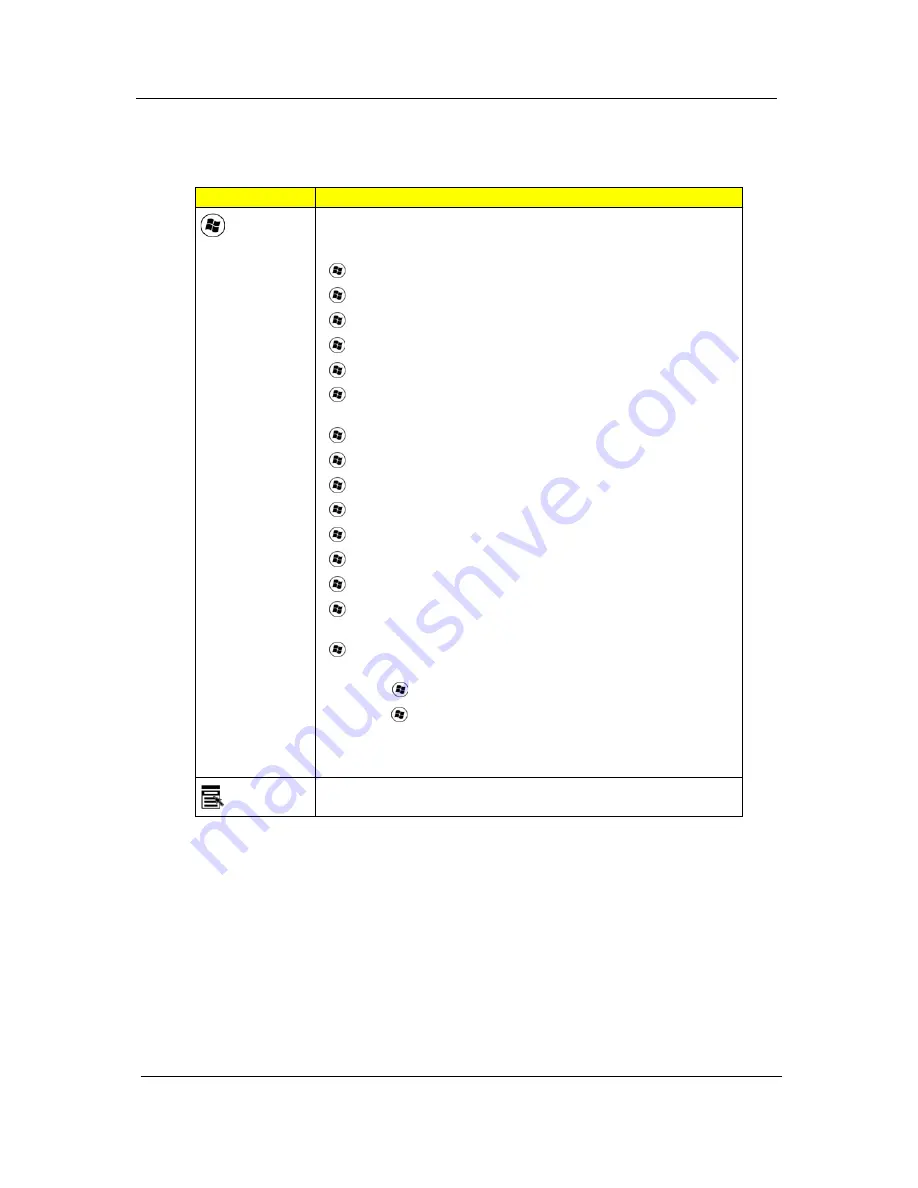
Windows Keys

The keyboard has two keys that perform Windows-specific functions.

Key

Description

Windows 
key

Pressed alone, this key has the same effect as clicking on the Windows 
Start button; it launches the Start menu. 
It can also be used with other keys to provide a variety of functions:

<

>  : 

Open or close the Start menu

<

> + <D>:

 Display the desktop

<

> + <E>: 

Open Windows Explore

<

> + <F>:

 Search for a file or folder

<

> + <G>:

 Cycle through Sidebar gadgets

<

> + <L>:

 Lock your computer (if you are connected to a network 

domain), or switch users (if you're not connected to a network domain)

<

> + <M>:

 Minimizes all windows

<

> + <R>: 

Open the Run dialog box

<

> + <T>: 

Cycle through programs on the taskbar

<

> + <U>: 

Open Ease of Access Center

<

> + <X>:

 Open Windows Mobility Center

<

> + <BREAK>: 

Display the System Properties dialog box

<

> + <SHIFT+M>:

 Restore minimized windows to the desktop

<

> + <TAB>: 

Cycle through programs on the taskbar by using 

Windows Flip 3-D

<

> + <SPACEBAR>: 

Bring all gadgets to the front and select Windows 

Sidebar

<CTRL> + <

> + <F>: 

Search for computers (if you are on a network)

<CTRL> + <

> + <TAB>:

 Use the arrow keys to cycle through programs 

on the taskbar by using Windows Flip 3-D

Note:

 Depending on your edition of Windows Vista or Windows XP, some 

shortcuts may not function as described.

Application 
key

This key has the same effect as clicking the right mouse button; it opens 
the application's context menu.

Summary of Contents for TravelMate 6293

Page 1: ...TravelMate 6293 Series Service Guide PRINTED IN TAIWAN Service guide files and updates are available on the ACER CSD web for more information please refer to http csd acer com tw ...

Page 2: ...II Revision History Please refer to the table below for the updates made on TravelMate 6293 Series service guide Date Chapter Updates ...

Page 3: ...pect to the contents hereof and specifically disclaims any warranties of merchantability or fitness for any particular purpose Any Acer Incorporated software described in this manual is sold or licensed as is Should the programs prove defective following their purchase the buyer and not Acer Incorporated its distributor or its dealer assumes the entire cost of all necessary servicing repair and an...

Page 4: ... bits and pieces of additional information related to the current topic WARNING Alerts you to any damage that might result from doing or not doing specific actions CAUTION Gives precautionary measures to avoid possible hardware or software problems IMPORTANT Reminds you to do specific actions relevant to the accomplishment of procedures ...

Page 5: ... NOT be covered in this generic service guide In such cases please contact your regional offices or the responsible personnel channel to provide you with further technical details 2 Please note WHEN ORDERING FRU PARTS that you should check the most up to date information available on your regional web or channel If for whatever reason a part number change is made it will not be noted in the printe...

Page 6: ...VI ...

Page 7: ... System Utilities 23 Navigating the BIOS Utility 24 Information 25 Main 26 Advanced 28 Security 29 Setting a Password 31 Removing a Password 31 Changing a Password 32 Boot 33 Exit 34 BIOS Flash Utility 35 HDD unlock Utility 36 Remove HDD Password 36 BIOS Flash SOP under DOS Mode 37 BIOS update SOP 37 Crisis disk creation 40 Crisis disk executing 44 Trouble shooting 45 Machine Disassembly and Repla...

Page 8: ...4 Remove LCM hinge screws 65 Remove CCD cable 66 Remove LCD panel 66 Troubleshooting 67 System Check Procedures 68 External Diskette Drive Check 68 External CD ROM Drive Check 68 Keyboard or Auxiliary Input Device Check 68 Memory check 69 Power System Check 69 Check the Power Adapter 69 Check the Battery Pack 69 Touchpad Check 70 Fingerprinter Function Check 70 5 in1 Card Reader Check 70 FIR Funct...

Page 9: ...z memory upgradeable to 4 GB using two soDIMM modules Display and Graphics 12 1 WXGA TFT LCD 1280 x 800 Mobile Intel GM45 Express Chipset Storage Subsystem 2 5 hard disk drive with enhanced Acer DASP Disk Anti Shock Protection Optical drive options z DVD Super Multi double layer drive z DVD CD RW combo drive 5 in 1 card reader supporting Secure Digital SD MultiMediaCard MMC Memory Stick MS Memory ...

Page 10: ...tform Module solution Kensington lock slot Dimensions Non 3G z 306 W x 227 D x 27 5 34 9 H mm 12 05 x 8 94 x 1 08 1 37 inches 3G z 306 W x 227 D x 27 5 36 9 H mm 12 05 x 8 94 x 1 08 1 45 inches 1 9 kg 4 3 lbs with 6 cell battery pack Power Subsystem ACPI 3 0 79 9 W 7200 mAh 58 8 W 4800 mAh 3 pin 65W AC adapter Input Devices 88 89 key keyboard Touchpad pointing device I O Ports Acer ezDock II II co...

Page 11: ...45 port Modem RJ 11 port DC in jack for AC adapter Environment Temperature z Operating 5 C to 35 C z Non operating 20 C to 65 C Humidity non condensing z Operating 20 to 80 z Non operating 20 to 80 NOTE only for certain models ...

Page 12: ...4 Chapter 1 System Block Diagram ...

Page 13: ... 2 CN2 LCM Cable CNTR 3 CN5 SIM card Board FFC CNTR For 3G SKU only 4 CN3 Modem card FFC CNTR 5 CN7 KeyBoard CNTR 6 CN6 Hot Key Board CNTR 7 CN4 BT cable CNTR 8 CN9 Touch Pad CNTR 9 CN11 PCMCIA CNTR 10 CN14 Card Reader CNTR 11 CN13 Modem card CNTR 12 CN15 Speaker Card CNTR 13 CN12 Express card CNTR 14 CN10 USB Port 15 CN8 USB Port ...

Page 14: ...ottom view No Name Description 1 CN601 USB Port 2 CN603 Battery CNTR 3 CN604 Docking CNTR 4 CN602 FAN Cable CNTR 5 Jack600 DC In Jack 6 CN600 VGA Port 7 Jack601 RJ45 8 CN608 HDD CNTR 9 CN609 Wirless Card CNTR 10 CN610 RTC Cattery Cable CNTR 11 Jack603 MIC Jack 12 Jack602 Earphone Jack ...

Page 15: ...Chapter 1 7 Your Acer Notebook tour After knowing your computer features let us show you around your new TravelMate computer Front View ...

Page 16: ... area for your hands when you use the computer 8 Touchpad Touch sensitive pointing device which functions like a computer mouse 9 Click buttons left center and right The left and right buttons function like the left and right mouse buttons The center button serves as Acer BioProtect fingerprint reader supporting Acer FingerNav 4 way control function only for certain model 11 Easy launch button But...

Page 17: ... printer and IR aware computer 5 Microphone jack Accepts input from external microphones 6 Headphones speaker line out jack Connects to audio line out devices e g speakers headphones No Icon Item Description 1 Ethernet RJ 45 port Connects to an Ethernet 10 100 1000 based network 2 Ventilation slots Enable the computer to stay cool even after prolonged use 3 Two USB 2 0 ports Connect to USB 2 0 dev...

Page 18: ...ical drive eject button Ejects the optical disk from the drive 5 Emergency eject hole Ejects the optical drive tray when the computer is turned off Note Insert a paper clip to the emergency eject hole to eject the optical drive tray when the computer is off 6 USB 2 0 ports Connect to USB 2 0 devices e g USB mouse USB camera 7 Modem RJ 11 port Connects to a phone line 8 Kensington lock slot Connect...

Page 19: ...II II connector Connects to Acer ezDock II II 5 Acer DASP Disk Anti Shock Protection Protects the hard disk drive from shocks and bumps only for certain models 6 Hard disk bay Houses the computer s hard disk secured with screws 7 Memory compartment Houses the computer s main memory 8 Ventilation slots and cooling fan Enable the computer to stay cool even after prolonged use Note Do not cover or ob...

Page 20: ...r of Windows applications NOTE1 When using the touchpad keep it and your fingers dry and clean The touchpad is sensitive to finger movement hence the lighter the touch the better the response Tapping harder will not increase the touchpad s responsiveness NOTE2 By default vertical and horizontal scrolling is enabled on your touchpad It can be disabled under Mouse settings in Windows Control Panel F...

Page 21: ...n F11 When Num Lock is on the embedded keypad is in numeric mode The keys function as a calculator complete with the arithmetic operators and Use this mode when you need to do a lot of numeric data entry A better solution would be to connect an external keypad Note Fn F11 only for certain models Scroll Lock Fn F12 When Scroll Lock is on the screen moves one line up or down when you press the up or...

Page 22: ...in M Minimizes all windows R Open the Run dialog box T Cycle through programs on the taskbar U Open Ease of Access Center X Open Windows Mobility Center BREAK Display the System Properties dialog box SHIFT M Restore minimized windows to the desktop TAB Cycle through programs on the taskbar by using Windows Flip 3 D SPACEBAR Bring all gadgets to the front and select Windows Sidebar CTRL F Search fo...

Page 23: ... processor 2 Either press at the bottom right of the keyboard or hold Shift and then press the 4 key at the upper center of the keyboard NOTE This function varies by the operating system version Hotkey Icon Function Description Fn F1 Hotkey help Displays help on hotkeys Fn F2 Acer eSettings Launches Acer eSettings in Acer Empowering Technology Fn F3 Acer ePower Management Launches Acer ePower Mana...

Page 24: ...ys enabled Cache scheme control Fixed in write back Item Specification Memory controller IntelGM45 Memory size 0MB no on board memory DIMM socket number 2 sockets Supports memory size per socket 2GB Supports maximum memory size 4GB Supports DIMM type DDR 3 Synchronous DRAM Supports DIMM Speed 800 1066 MHz Supports DIMM voltage 1 5V and 0 75V Supports DIMM package 204 pin soDIMM Item Specification ...

Page 25: ...al Supported radio frequency bands UMTS HSDPA1 GTM380W 850 MHz 1900 MHz and 2100 MH GTM380E 850 MHz 1900 MHz and 2100 MHz GTM380JD 800 MHz 1700 MHz and 2100 MHz GSM GPRS EDGE GTM380W 850 MHz 900 MHz 1800 MHz and the 1900 MHz GTM380E 850 MHz 900 MHz 1800 MHz and the 1900 MHz GPS2 L1 band 1575 42 MHz Item Specification Chipset Built in ICH9 Data throughput 723 bps full speed data rate Protocol Bluet...

Page 26: ...0827AS Capacity GB 120 160 250 320 Bytes per sector 512 Data heads 2 4 for Toshiba and HGST 4 Drive Format Disks 1 Spindle speed RPM 5400 RPM Performance Specifications Buffer size 8M Interface SATA Max media transfer rate disk buffer Mbytes s 100 150 Data transfer rate host buffer Mbytes s Ultra DMA mode 5 100 MB Sec DC Power Requirements Voltage tolerance 5V DC 5 ...

Page 27: ...a in each CD ROM CD ROM XA CD 1 Video CD CD Extra and CD Plus 2 Reads data in super Audio CD SACD Hybrid type 3 Reads standard CD DA 4 Reads and writes CD R discs 5 Reads and writes CD RW andHSRW discs 6 Reads and writes US US RW 7 Reads data in each DVD ROM and DVD Dual 8 Reads and writes in each DVD R Ver 2 0 for general DVD RW and DVD R RW Ver1 1 9 Reads and writes DVD R Dual 10 Reads and write...

Page 28: ...s Supports PnP DMA channel DMA channel 0 Item Specification Chipset Intel GM46 Video Memory 64M Item Specification Chipset Built in ICH9M USB Compliancy Level 2 OHCI USB 2 0 Host controller Number of USB port 3 Location One on the right side two on the left right side Serial port function control Enable Disable by BIOS Setup Item Specification Core logic Intel GM45 ICH9M VGA Internal Graphics LAN ...

Page 29: ...rallel Normal voltage 11 1V Charge voltage 12 6V Item Specification Vendor model name AUO 12 1 WXGA None Glare B121EW03 TOSHIBA 12 1 WXGA Glare LTD121 Screen Diagonal mm 12 1 inches Active Area mm 163 2 H x 261 12 W mm Display resolution pixels 1280 x 800 XGA WIDE Pixel Pitch 0 204 H x 0 204 W mm Pixel Arrangement R G B Vertical Stripe Display Mode Normally White Typical White Luminance cd m2 210 ...

Page 30: ...rrent 1 6A Inrush current 50A 115VAC 100A 230VAC Efficiency 85 min 115VAC input full load Item Specification Mech Off G3 All devices in the system are turned off completely Soft Off G2 S5 OS initiated shutdown All devices in the system are turned off completely Working G0 S0 Individual devices such as the CPU and hard disc may be power managed in this state Suspend to RAM S3 CPU set power down VGA...

Page 31: ...device without entering BIOS Setup Utility please set the parameter to enabled Press F12 during POST to enter multi boot menu In this menu user can change boot device without entering BIOS SETUP Utility Phoenix TrustedCore Setup Utility Information Main Advanced Security Boot Exit CPU Type Genuine Intel R CPU Xxxx CPU Speed XXXX GHz IDE0 Model Name TOSHIBA MK3018GAP PM Note IDE0 Serial No Y2554027...

Page 32: ...ess Esc while you are in any of the menu options to go to the Exit menu In any menu you can load default settings by pressing F9 You can also press F10 to save any changes made and exit the BIOS Setup Utility NOTE You can change the value of a parameter if it is enclosed in square brackets Navigation keys for a particular menu are shown on the bottom of the screen Help for parameters are found in ...

Page 33: ...are version of the system KBC Ver This field shows the keyboard Serial Number This field displays the serial number of this unit Asset Tag Number This field displays the asset tag number of the system Product Name This field shows product name of the system Manufacturer Name This field displays the manufacturer of this system UUID Number This will be visible only when an internal LAN device is pre...

Page 34: ...fer Phoenix TrustedCore Setup Utility Information Main Advanced Security Boot Exit Item specific Help System Time 09 00 00 System Date 01 01 2007 Tab Shift Tab or Enter selects field Total Memory XXXX MB Video Memory 8M Note2 Quiet Boot Enabled Power on display Auto Network Boot Enabled F12 Boot Menu Disabled D2D Recovery Enabled SATA Mode AHCI Mode F1 Help Select Item F5 F6 Change Values F9 Setup...

Page 35: ...es if Customer Logo will be displayed or not shows Summary Screen is disabled or enabled Enabled Customer Logo is displayed and Summary Screen is disabled Disabled Customer Logo is not displayed and Summary Screen is enabled Option Enabled or Disabled Power on display Auto During power process the system will detect if any display device is connected on external video port If any external display ...

Page 36: ...tion Format Option Serial port Displays the settings of the serial port Enabled or Disabled Parallel port Shows the settings of the parallel port Enabled or Disabled Phoenix TrustedCore Setup Utility Information Main Advanced Security Boot Exit Serial Port Auto Infrared Port FIR Auto Parallel Port Auto Mode ECP ASF Configuration F1 Help Select Item F5 F6 Change Values F9 Setup defaults Esc Exit Se...

Page 37: ...curity Boot Exit Item specific Help Supervisor Password Is Clear User Password Is Clear HDD Password Is Clear Note1 Set Supervisor Password Enter Set User Password Enter Set HDD Password Enter Password on Boot Disabled Currernt TPM StateNote4 Change TPM State Note5 No Change F1 Help Select Item F5 F6 Change Values F9 Setup defaults Esc Exit Select Menu Enter Select4Sub Menu F10 Save and Exit ...

Page 38: ...e user password When user password is set this password protects the BIOS Setup Utility from unauthorized access The user can enter Setup menu only and does not have right to change the value of parameters Set Supervisor Password Press Enter to set the supervisor password When set this password protects the BIOS Setup Utility from unauthorized access The user can not either enter the Setup menu no...

Page 39: ... Press e After setting the password the computer sets the User Password parameter to Set 4 If desired you can opt to enable the Password on boot parameter 5 When you are done press u to save the changes and exit the BIOS Setup Utility Removing a Password Follow these steps 1 Use the w and y keys to highlight the Set Supervisor Password parameter and press the e key The Set Password box appears 2 T...

Page 40: ...ng the password the computer sets the User Password parameter to Set 5 If desired you can enable the Password on boot parameter 6 When you are done press u to save the changes and exit the BIOS Setup Utility If the verification is OK the screen will display as following The password setting is complete after the user presses u If the current password entered does not match the actual current passw...

Page 41: ...p Utility Information Main Advanced Security Boot Exit Item specific Help Boot prioroty order 1 IDE0 WDC WD200EB PM 2 IDE1 WDC WD200EB PM 3 CD DVD 4 Network boot 5 USB HDD 6 USB FDD 7 USB Key 8 USB CD DVD ROM Use or to select a device then press F6 to move it up the List or F5 to move it down the list Press Esc to escape the menu F1 Help Select Item F5 F6 Change Values F9 Setup defaults Esc Exit S...

Page 42: ...values for all SETUP item Discard Changes Load previous values from CMOS for all SETUP items Save Changes Save Setup Data to CMOS Phoenix TrustedCore Setup Utility Information Main Advanced Security Boot Exit Item specific Help Exit Saving Changes Exit System Setup and save your changes to CMOS Exit Discarding Changes Exit utility without saving Setup data to CMOS Load Setup Defaults Load default ...

Page 43: ... Diskette before you use the Phlash utility NOTE Do not install memory related drivers XMS EMS DPMI when you use the Phlash NOTE Please use the AC adaptor power supply when you run the Phlash utility If the battery pack does not contain enough power to finish BIOS flash you may not boot the system because the BIOS is not completely loaded Fellow the steps below to run the Phlash 1 Prepare a bootab...

Page 44: ...e HDD password error code would display on the screen See the image below If you need to solve HDD password locked problem you can run unlock6 EXE 1 Key in unlock6 error code 205 2 Select 2 3 Choose one HDD password Reboot system and key in R6PI11X or MI8N4KK to HDD user password Then the HDD password will be unlocked and will auto into Windows after reboot ...

Page 45: ...r DOS Mode 1 USB Floppy into DOS Mode 2 Dos mode run phlash16 xxx rom 3 Restart System BIOS update SOP 1 Go to SWinFlashn Applicaion Properties Compatibility 2 Select Compatibility Privilege Level Run this program as an administrator ...

Page 46: ...38 Chapter 2 3 Execute SWin Flash Application 4 Select new BIOS update 5 Run Flash BIOS ...

Page 47: ...ning v Load new BIOS v Analyze old and new BIOS v Compatibility v Read old BIOS v Save old BIOS to Backup file v Flash new BIOS System BIOS was success update 8 System will be shut down NOTE 1 Please input AC adapter when flash BIOS 2 Close all application when flash BIOS ...

Page 48: ...40 Chapter 2 Crisis disk creation 1 UnZIP the CRISDISK file 2 Download a new BIOS rename the BIOS to BIOS WPH 3 Open the CRISDISK file run the WINCRIS 4 Press Start ...

Page 49: ...Chapter 2 41 5 Press 確定 6 Press Start 7 Press 確定 8 Wait the disk format complete ...

Page 50: ...42 Chapter 2 9 Press 確定 10 Press 關閉 11 Wait for the system to create the disk 12 Press 確定 when it s completed ...

Page 51: ...Chapter 2 43 13 Press 否 14 nsert Floppy with the Crisis disk on system ...

Page 52: ...will power on for 1 second then release all key pads 2 When system power off press Fn Esc and wait for system to power on again about 4 seconds 3 Crisis disk executing FDD should be reading for about 15 seconds 4 System will power off on crisis disk executing completion 5 Reboot system ...

Page 53: ...Chapter 2 45 Trouble shooting 1 If Crisis disk is not working please check the status of bios wph file 2 To fix incorrect bios wph file format please uncheck hide extensions for known file types ...

Page 54: ...46 Chapter 2 3 Rename it to bios wph ...

Page 55: ...t grounding strap and conductive mat for preventing electrostatic discharge Flat screwdriver Small Philips screwdriver Hex screwdriver Plastic flat head screwdriver Plastic tweezers NOTE The screws for the different components vary in size During the disassembly process group the screws with the corresponding components to avoid mismatch when putting back the components Chapter 3 Machine Disassemb...

Page 56: ...dule Bluetooth 4 3 1 Base screw list No SPEC Qty Location 1 6052B0118301 M2x4 5 40Dx08T 21 Base MB Cardbus Odd Cntr BTCB Speaker 13 6 2 2 6052A0051101 M2x3 5 40Dx08T 1 TPCB Kensington Lock 3 6052A0050703 M2x2 0 68Dx05T 4 TPCB Hotkey B Button B 4 6052B0120001 M2x2 5 40Dx05T 28 Base thermal Sim pcb 3G Power pcb TPCB ODD Bracket 7 7 2 2 8 2 5 60520D065905 M2x2 0 35Dx03T 1 TPCB HDD Lens 6 6052B0125901...

Page 57: ... representation on the entire disassembly sequence and instructs you on the components that need to be removed during servicing For example if you want to remove the system board you must first remove the keyboard then disassemble the inside assembly frame in that order Main unit disassembly flow chart ...

Page 58: ...50 Chapter 3 LCM module disassembly flow chart ...

Page 59: ...Chapter 3 51 Removing the Battery Pack 1 Release the battery 2 Slide the battery latch then remove the battery ...

Page 60: ...2 Chapter 3 Removing the HDD Wirless Card RAM Module ODD Express Dummy Card Card Reader Dummy Module Removing CTO Cover 1 Loose 6 CTO cover screws 2 Remove CTO cover Removing the HDD 3 Remove HDD module ...

Page 61: ...Chapter 3 53 Removing the Wirless Card 4 Remove Wireless card antenna 5 Remove Wireless card Removing RAM Module 6 Release RAM module from RAM socket ...

Page 62: ...54 Chapter 3 7 Remove RAM module Removing BTCB Screws 8 Loose and remove BTCB screws X 16 Removing ODD Express Dummy Card Dummy Card Reader 9 Remove ODD module ...

Page 63: ...Chapter 3 55 10 Press express card latch and remove express dummy card 11 Push dummy card reader and remove the dummy card Remove Switch Cover 12 Pull Switch cover up ...

Page 64: ...56 Chapter 3 13 Reverse Switch cover 14 Disconnect Power B FFC from the Switch cover Remove Keyboard 15 Pull Keyboard up ...

Page 65: ...Chapter 3 57 16 Reverse Keyboard 17 Disconnect K B FFC from the MB Remove 3G SIM Card B Hotkey B 18 Loose 3G SIM card board screws X 2 Disconnect SIM card boardFFC ...

Page 66: ...58 Chapter 3 19 Loose Hotkey board screws X 2 Disconnect Hotkey board FFC Remove Wireless Antenna from TPCB 20 Remove Wireless antenna from the TPCB ...

Page 67: ...Chapter 3 59 Disconnect 3G wireless antenna cable 21 Disconnect 3G module antenna Disconnect LCM cable Touchpad FFC BT cable 22 Disconnect LCM cable ...

Page 68: ...60 Chapter 3 23 Disconnect Touchpad FFC 24 Disconnect BT cable ...

Page 69: ...Chapter 3 61 Disassemble LCM screws 25 Loose LCM screws X 4 26 Remove LCM module Disassemble TPCB 27 Loose TPCB screws X 3 ...

Page 70: ...62 Chapter 3 28 Remove TPCB Disconnect Modem cable Wireless card cable Speaker cable 29 Disconnect Modem cable 30 Disconnect Wireless cable 31 Disconnect Speaker cable ...

Page 71: ...Chapter 3 63 Remove Main board 32 Remove M B from the BTCB ...

Page 72: ...64 Chapter 3 Disassembly LCM module Remove LCM bezel 3 Remove six LCM bezel mylar 4 Remove LCM bezel Remove Inverter board 5 Disconnect Inverter cables ...

Page 73: ...Chapter 3 65 6 Remove Inverter board Remove LCM hinge screws 7 Loose LCM hinge screws Left side X 3 8 Loose LCM hinge screws Right side X 3 ...

Page 74: ...66 Chapter 3 Remove CCD cable 9 Disconnect CCD cable Remove LCD panel 10 Remove LCD panel from the TPDL ...

Page 75: ... to determine which page to go to Symptoms Verified Go To Power failure The power indicator does not go on or stay on Power System Check on page 69 POST does not complete No beep or error codes are indicated Fingerprinter Function Check on page 70 Undetermined Problems on page 83 POST detects an error and displayed messages on screen Error Messages List on page 72 Other symptoms i e LCD display pr...

Page 76: ...e the drive to fail Do the following to select the test device 1 Boot from the diagnostics diskette and start the diagnostics program 2 See if CD ROM Test is passed when the program runs to CD ROM Test 3 Follow the instructions in the message window If an error occurs reconnect the connector on the System board If the error still remains 1 Reconnect the external diskette drive CD ROM module 2 Repl...

Page 77: ...heck the Power Adapter Unplug the power adapter cable from the computer and measure the output voltage at the plug of the power adapter cable See the following figure 1 If the voltage is not correct replace the power adapter 2 If the voltage is within the range do the following Replace the System board If the problem is not corrected see Undetermined Problems on page 83 If the voltage is not corre...

Page 78: ...s on the screen for a short time This self acting pointer movement can occur when a slight steady pressure is applied to the touchpad pointer This symptom is not a hardware problem No service actions are necessary if the pointer movement stops in a short period of time Fingerprinter Function Check If the fingerprinter doesn t work do the following to correct the problem 1 Reboot machine and turn f...

Page 79: ...rmation about a hardware device e g the amount of memory installed Others may indicate a problem with a device such as the way it has been configured NOTE If the system fails after you make changes in the BIOS Setup Utility menus reset the computer enter Setup and install Setup defaults or correct the error Index of Error Messages Error Code List Error Codes Error Messages 006 Equipment Configurat...

Page 80: ...reboot system System CMOS checksum bad Default configuration used RTC battery Run BIOS Setup Utility to reconfigure system time then reboot system System timer error RTC battery Run BIOS Setup Utility to reconfigure system time then reboot system System board Real time clock error RTC battery Run BIOS Setup Utility to reconfigure system time then reboot system System board Previous boot incomplete...

Page 81: ...em board Failing Bits nnnn DIMM BIOS ROM System board Fixed Disk n None Invalid System Configuration Data BIOS ROM System board I O device IRQ conflict Run Load Default Settings in BIOS Setup Utility RTC battery System board Operating system not found Enter Setup and see if fixed disk and drive A are properly identified Diskette drive Hard disk drive System board Error Messages FRU Action in Seque...

Page 82: ...ower source battery pack and power adapter See Power System Check on page 69 Reconnect the LCD connector Hard disk drive LCD inverter ID LCD cable LCD Inverter LCD System board No beep power on indicator turns on and LCD is blank But you can see POST on an external CRT Reconnect the LCD connectors LCD inverter ID LCD cable LCD inverter LCD System board No beep power on indicator turns on and a bli...

Page 83: ... initialization 1Ch Reset Programmable Interrupt Controller 20h 1 3 1 1 Test DRAM refresh 22h 1 3 1 3 Test 8742 Keyboard Controller 24h Set ES segment register to 4 GB 26h Enable A20 line 28h Autosize DRAM 29h Initialize POST Memory Manager 2Ah Clear 215 KB base RAM 2Ch 1 3 4 1 RAM failure on address line xxxx 2Eh 1 3 4 3 RAM failure on data bits xxxx of low byte of memory bus 2Fh Enable cache bef...

Page 84: ...Enable external and CPU caches 69h Setup System Management Mode SMM area 6Ah Display external L2 cache size 6Bh Load custom defaults optional 6Ch Display shadow area message 6Eh Display possible high address for UMB recovery 70h Display error messages 72h Check for configuration errors 76h Check for keyboard errors 7Ch Set up hardware interrupt vectors 7Eh Initialize coprocessor if present 80h Dis...

Page 85: ...h Erase F2 prompt AAh Scan for F2 key stroke ACh Enter SETUP AEh Clear Boot flag B0h Check for errors B2h POST done prepare to boot operating system B4h 1 One short beep before boot B5h Terminate QuietBoot optional B6h Check password optional B9h Prepare Boot BAh Initialize DMI parameters BBh Initialize PnP Option ROMs BCh Clear parity checkers BDh Display MultiBoot menu BEh Clear screen optional ...

Page 86: ...ti Processor EAh Initialize OEM special code EBh Initialize PIC and DMA ECh Initialize Memory type EDh Initialize Memory size EEh Shadow Boot Block EFh System memory test F0h Initialize interrupt vectors F1h Initialize Run Time Clock F2h Initialize video F3h Initialize System Management Mode F4h 1 Output one beep before boot F5h Boot to Mini DOS F6h Clear Huge Segment F7h Boot to Full DOS Code Bee...

Page 87: ...yboard if contrast and brightness function key doesn t work LCD inverter ID LCD cable LCD inverter LCD System board Unreadable LCD screen Missing pels in characters Abnormal screen Wrong color displayed Reconnect the LCD connector LCD inverter ID LCD cable LCD inverter LCD System board LCD has extra horizontal or vertical lines displayed LCD inverter ID LCD inverter LCD cable LCD System board Symp...

Page 88: ...battery pack and power adapter See Power System Check on page 69 Hold and press the power switch for more than 4 seconds System board Battery can t be charged See Check the Battery Pack on page 69 Battery pack System board Symptom Error Action in Sequence System cannot detect the PC Card PCMCIA PCMCIA slot assembly System board PCMCIA slot pin is damaged PCMCIA slot assembly Symptom Error Action i...

Page 89: ...dby mode after closing the LCD See Save to Disk S4 on page 22 LCD cover switch System board The system doesn t resume from hibernation mode See Save to Disk S4 on page 22 Hard disk connection board Hard disk drive System board The system doesn t resume from standby mode after opening the LCD See Save to Disk S4 on page 22 LCD cover switch System board Battery fuel gauge in Windows doesn t go highe...

Page 90: ...te Load Default Settings then reboot system Reconnect hard disk CD ROM diskette drives External display does not work correctly Press Fn F5 LCD CRT Both display switching System board USB does not work correctly System board Symptom Error Action in Sequence Keyboard one or more keys does not work Reconnect the keyboard cable Keyboard System board Touchpad does not work Reconnect touchpad cable Tou...

Page 91: ...r a short circuit is suspected or whether the system is inoperative Follow these procedures to isolate the failing FRU do not isolate non defective FRU NOTE Verify that all attached devices are supported by the computer NOTE Verify that the power supply being used at the time of the failure is operating correctly See Power System Check on page 69 1 Power off the computer 2 Visually check them for ...

Page 92: ...84 Chapter 4 ...

Page 93: ... SIM card Board FFC CNTR For 3G SKU only 4 CN3 Modem card FFC CNTR 5 CN7 KeyBoard CNTR 6 CN6 Hot Key Board CNTR 7 CN4 BT cable CNTR 8 CN9 Touch Pad CNTR 9 CN11 PCMCIA CNTR 10 CN14 Card Reader CNTR 11 CN13 Modem card CNTR 12 CN15 Speaker Card CNTR 13 CN12 Express card CNTR 14 CN10 USB Port 15 CN8 USB Port Jumper and Connector Locations Chapter 5 ...

Page 94: ...ottom view No Name Description 1 CN601 USB Port 2 CN603 Battery CNTR 3 CN604 Docking CNTR 4 CN602 FAN Cable CNTR 5 Jack600 DC In Jack 6 CN600 VGA Port 7 Jack601 RJ45 8 CN608 HDD CNTR 9 CN609 Wirless Card CNTR 10 CN610 RTC Cattery Cable CNTR 11 Jack603 MIC Jack 12 Jack602 Earphone Jack ...

Page 95: ... made it will not be noted on the printed Service Guide For ACER AUTHORIZED SERVICE PROVIDERS your Acer office may have a DIFFERENT part number code from those given in the FRU list of this printed Service Guide You MUST use the local FRU list provided by your regional Acer office to order FRU parts for repair and service of customer machines NOTE To scrap or to return the defective parts you shou...

Page 96: ...88 Chapter 6 TravelMate 6293 Exploded Diagram ...

Page 97: ... SADP 65KB BFJA LF LEVEL 4 FOR OBL ONLY AP 06501 014 Category Part Name and Description Acer Part No BATTERY LI ION 6CELL SANYO TM 2007A 3S2P 4400MAH BT 00603 044 BATTERY LI ION 6CELL SONY TM 2007A 3S2P 4400MAH BT 00604 027 BATTERY LI ION 6CELL PANASONIC TM 2007A 3S2P 4400MAH PSS BT 00605 024 BATTERY LI ION 6CELL SIMPLO TM 2007A 3S2P 4400MAH PSS BT 00607 018 BATTERY LI ION 9CELL SONY TM 2007A 3S3P...

Page 98: ...G FX 22500 021 BLUETOOTH BOARD FOXCONN BCM2045 V2 T60H928 11 BT 21100 005 WIRELESS LAN BOARD 512AN_MMWG SHIRLEY PEAK 5100 MM 895361 KI SPM01 003 WIRELESS LAN BOARD 533AN_MMWG SHIRLEY PEAK MM 895362 KI SPM01 001 WIRELESS LAN BOARD 512AN_HMWG SHIRLEY PEAK 5100 MM 895373 HALF MINI CARD KI SPH01 003 WIRELESS LAN BOARD 533AN_HMWG SHIRLEY PEAK MM 895401 HALF MINI CARD KI SPH01 001 WWAN 3G MODULE MINI PC...

Page 99: ... 3G SIMM BOARD CABLE 50 TQK0N 001 MODEM CABLE WITH RJ11 CONNECTOR 50 TQP0N 005 CORD ROUND 3POS 1828mm E POWER USA 27 AAMVN 001 CORD ROUND 3POS 1850mm E POWER EUR 27 AAMVN 002 POWER CORD 3PIN SOUTH AFRICA 27 AAMVN 008 POWER CORD 3PIN DENMARK 27 AAMVN 010 POWER CORD ISRAEL 27 AAMVN 011 POWER CORD 3PIN ITALIAN 27 AAMVN 009 POWER CORD 3PIN UK 27 AAMVN 004 POWER CORD 3PIN SWISS 27 AAMVN 006 POWER CORD ...

Page 100: ... Category Part Name and Description Acer Part No LCD COVER 12 1 W ANTENNA 3G 60 TQK0N 003 LCD COVER 12 1 W ANTENNA 60 TQP0N 005 UPPER CASE WITH FINGER PRINT HOLE 60 TQP0N 002 UPPER CASE W O FINGER PRINT HOLE 60 TQK0N 002 LOWER CASE 3G 60 TQK0N 001 LOWER CASE 60 TQP0N 001 LCD BEZEL 12 1 60 TQP0N 004 LCD BRACKET LEFT 33 TQP0N 004 LCD BRACKET RIGHT 33 TQP0N 003 ...

Page 101: ... COMBO BEZEL 42 TQP0N 007 OPTICAL BRACKET 33 TQP0N 001 HDD HOLDER 42 TLK0N 006 UNITLOAD COVER 42 TQP0N 002 MIDDLE COVER 3G 42 TQK0N 001 MIDDLE COVER 42 TQP0N 001 HDD CONNECTOR 20 TLK0N 001 HALF MINI CARD BRACKET 33 TQP0N 002 Category Part Name and Description Acer Part No ...

Page 102: ... 3M 1066 25W KC 84001 DPP Category Part Name and Description Acer Part No ODD SONY COMBO 12 7MM TRAY DL 24X CRX 890S LF W O BEZEL SATA KO 0240E 009 ODD PANASONIC SUPER MULTI DRIVE 12 7MM TRAY DL 8X UJ 870A LF W O BEZEL SATA KU 00807 059 ODD HLDS SUPER MULTI DRIVE 12 7MM TRAY DL 8X GSA T50N LF W O BEZEL SATA KU 0080D 029 ODD HLDS SUPER MULTI DRIVE 12 7MM TRAY DL 8X GSA T50N LF W O BEZEL SATA MALAYS...

Page 103: ...X LEO BS LF F W LB113J KH 16004 002 HDD 160GB 5400RPM SATA II HGST HTS542516K9SA00 BRONCO B LF F W C31P KH 16007 016 HDD 160GB 5400RPM SATA WD WD1600BEVT 22ZCTO ML160 LF F W 11 01A11 KH 16008 022 HDD 250GB 5400RPM SATA SEAGATE ST9250827AS CORSAIR LF F W 3 AAA KH 25001 011 HDD 250GB 5400RPM SATA TOSHIBA MK2546GSX LEO BS LF F W LB013J KH 25004 001 HDD 250GB 5400RPM SATA II HGST HTS542525K9SA00 LF F ...

Page 104: ...KB FV3 88KS BLACK RUSSIAN KB INT00 343 KEYBOARD 12_13KB FV3 89KS BLACK PORTUGUESE KB INT00 344 KEYBOARD 12_13KB FV3 89KS BLACK POLISH KB INT00 345 KEYBOARD 12_13KB FV3 89KS BLACK NORWEGIAN KB INT00 346 KEYBOARD 12_13KB FV3 89KS BLACK LUXEMBOURGISH KB INT00 347 KEYBOARD 12_13KB FV3 88KS BLACK KOREAN KB INT00 348 KEYBOARD 12_13KB FV3 92KS BLACK JAPANESE KB INT00 349 KEYBOARD 12_13KB FV3 89KS BLACK I...

Page 105: ...KEYBOARD 12_13KB FV3 89KS BLACK ENGLISH CANADIAN FRENCH KB INT00 368 Category Part Name and Description Acer Part No LCD 12 1 WXGA NONE GLARE AU B121EW03 V6 LF 220NIT 16MS LK 12105 013 LCD 12 1 WXGA NONE GLARE TOSHIBA TD121EXEV LF 200NIT 25MS LK 1210F 017 LCD 12 1 WXGA GLARE AU B121EW03 V7 LF 220NIT 16MS LK 12105 012 LED LCD 12 1 WXGA GLARE AU B121EW09 V0 LF 220NIT 16MS LK 12105 014 LED LCD 12 1 W...

Page 106: ...2GB04 004 SO DIMM 2GB DDRIII1066 ELPIDA EBJ21UE8BAU0 AE E LF 128 8 0 07um KN 2GB09 002 SO DIMM 2GB DDRIII1066 SAMSUNG M471B5673DZ1 CF8 LF KN 2GB0B 005 Category Part Name and Description Acer Part No MICROPHONE 23 TQP0N 003 Category Part Name and Description Acer Part No LCD CUSHION UP 47 TQP0N 002 LCD CUSHION DOWN 47 TQP0N 001 HDD INSULATOR 47 TLK0N 005 RUBBER FOOT LEFT 47 TQP0N 003 RUBBER FOOT MI...

Page 107: ... 2 0MM CROSS NI 86 TQP0N 001 SCREW M2 5 2 5MM CROSS BNI PATCH 86 TQP0N 002 SCREW M2 0 4 5MM CROSS BNI PATCH 86 TQP0N 003 SCREW M2 0 2 5MM CROSS BNI PATCH 86 TQP0N 004 SCREW M2 0 6 0MM CROSS BNI PATCH 86 TQP0N 005 SCREW M2 0 4 0MM CROSS NI PATCH 86 TQP0N 006 Category Part Name and Description Acer Part No SPEAKER SET 23 TQP0N 001 Category Part Name and Description Acer Part No ...

Page 108: ...100 Chapter 6 ...

Reviews: