152
Chapter 5
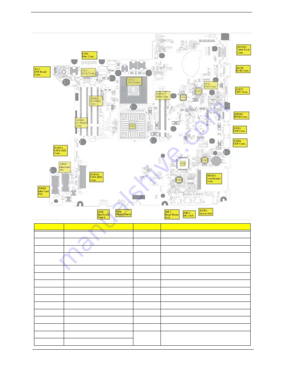
Bottom View
Location
Description
Location
Description
JP11
USB Board Conn.
JSATA2
SATA HDD Conn.
JP12
FAN Conn.
JMINI1
Mini Card Slot
PJP1
DC-in Cable Conn.
JMINI2
Mini Card Slot (WLAN)
PJP2
Battery Pin Header (connection
with Battery Board)
JDIMM1
SO-DIMM Slot
JDOCK1
Cable Dock Conn.
JDIMM2
SO-DIMM Slot
JRJ45
RJ45 Conn.
JCPU1
CPU Socket
JCRT1
CRT Conn.
SW3
WLAN Switch
JHDMI1
HDMI Conn.
SW4
Bluetooth Switch
JUSB1
USB Conn.
U30
North Bridge
JUSB2
USB Conn.
U23
Giga LAN Controller (BCM5764M)
JREAD1
Card Reader Conn.
U24
DVI/ HDMI Switch (PI3HDMI412ADZBEX)
JLINE1
Line-in JACK
U32
Card Reader Host Controller (JMB385)
JMIC1
Mic. JACK
U34
PCMCIA Controller (OZ601TN)
JHP1
Headphone out JACK
U36
Audio Codec (ALC268)
JSATA1
SATA ODD Conn.
Summary of Contents for TravelMate 4330 Series
Page 6: ...VI ...
Page 10: ...X Table of Contents ...
Page 14: ...4 Chapter 1 System Block Diagram ...
Page 38: ...28 Chapter 1 ...
Page 56: ...46 Chapter 2 ...
Page 64: ...54 Chapter 3 5 Remove the WLAN cover as shown ...
Page 86: ...76 Chapter 3 8 The Upper Cover can now be removed from the lower base ...
Page 101: ...Chapter 3 91 4 Lift the Thermal Module clear of the Mainboard ...
Page 120: ...110 Chapter 3 3 Connect the RJ 11 cable to the modem module as shown ...
Page 134: ...124 Chapter 3 3 Turn the computer over and replace the five securing screws ...
Page 181: ...Chapter 6 171 ...
Page 203: ...193 Appendix A ...
Page 204: ...Appendix A 194 ...
Page 212: ...202 Appendix B ...
Page 214: ...204 Appendix C ...
Page 217: ...207 Wireless Function Failure 142 WLAN Board 56 ...
Page 218: ...208 ...


