


Chapter 2
31
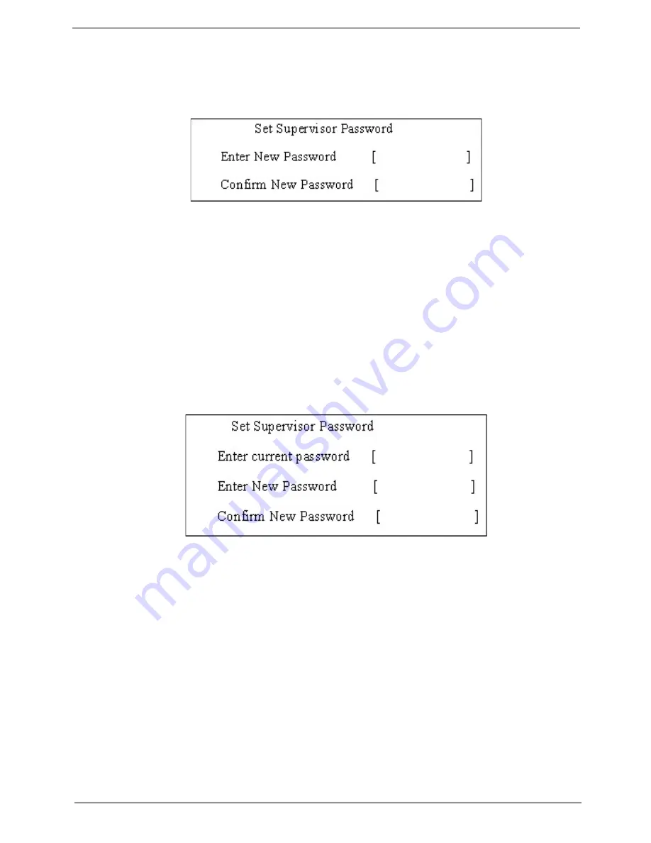
Setting a Password
Follow these steps as you set the user or the supervisor password:
1.
Use the
↑
and
↓
keys to highlight the Set Supervisor Password parameter and press the
Enter
key. The
Set Supervisor Password box appears:
2.
Type a password in the “Enter New Password” field. The password length can not exceeds 8
alphanumeric characters (A-Z, a-z, 0-9, not case sensitive). Retype the password in the “Confirm New
Password” field.
IMPORTANT:
Be very careful when typing your password because the characters do not appear on the screen.
3.
Press
Enter
.
After setting the password, the computer sets the User Password parameter to “Set”.
4.
If desired, you can opt to enable the Password on boot parameter.
5.
When you are done, press F10 to save the changes and exit the BIOS Setup Utility.
Removing a Password
Follow these steps:
1.
Use the
↑
and
↓
keys to highlight the Set Supervisor Password parameter and press the
Enter
key. The
Set Password box appears:
2.
Type the current password in the Enter Current Password field and press
Enter
.
3.
Press
Enter
twice
without
typing anything in the Enter New Password and Confirm New Password fields.
The computer then sets the Supervisor Password parameter to “Clear”.
4.
When you have changed the settings, press
u
to save the changes and exit the BIOS Setup Utility.
Summary of Contents for LX.AUQ0X.080 - Aspire 6530-5195 - Athlon X2 1.9 GHz
Page 6: ...VI ...
Page 10: ...X Table of Contents ...
Page 14: ...4 Chapter 1 System Block Diagram ...
Page 50: ...40 Chapter 2 ...
Page 85: ...Chapter 3 75 4 Grasp the module by the right side and lift up to remove ...
Page 93: ...Chapter 3 83 7 Disconnect the Mic cable and remove the LCD bezel ...
Page 104: ...94 Chapter 3 4 Replace the ten securing screws and screw caps on the LCD bezel ...
Page 106: ...96 Chapter 3 3 Connect fan cable to the mainboard as shown ...
Page 111: ...Chapter 3 101 2 Reconnect the TouchPad and Finger Print Reader FFCs as shown ...
Page 120: ...110 Chapter 3 7 Turn the computer over and replace the ten screws as shown ...
Page 155: ...Chapter 5 145 Jumper and Connector Locations Top View Chapter 5 ...
Page 156: ...146 Chapter 5 Bottom View ...
Page 173: ...Chapter 6 163 ...
Page 220: ...210 Appendix B ...
Page 222: ...212 Appendix C ...