Chapter 2
41
Miscellaneous Utilities
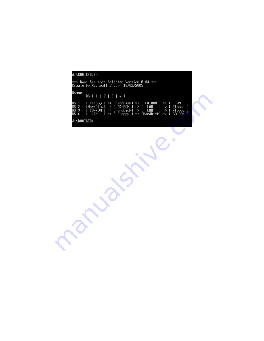
Using Boot Sequence Selector
Boot Sequence Selector allows the boot order to be changes without accessing the BIOS. To use Boot
Sequence Selector, perform the following steps:
1.
Enter into DOS.
2.
Execute
BS.exe
to display the usage screen.
3.
Select the desired boot sequence by entering the corresponding sequence, for example, enter
BS2
to
change the boot sequence to HDD|CD ROM|LAN|Floppy.
Using DMITools
The DMI (Desktop Management Interface) Tool copies BIOS information to eeprom to be used in the DMI pool
for hardware management.
When the BIOS displays
Verifying DMI pool data
it is checking the table correlates with the hardware before
sending to the operating system (Windows, etc.).
To update the DMI Pool, perform the following steps:
1.
Enter into DOS.
2.
Execute
dmitools
. The following messages show dmitools usage:
•
dmitools /r ==> Read dmi string from memory
•
dmitools /wm xxxx ==> Write manufacturer name to EEPROM (max. 16 characters)
•
dmitools /wp xxxx ==> Write product name to EEPROM (max. 16 characters)
•
dmitools /ws xxxx ==> Write serial number to EEPROM (max. 22 characters)
•
dmitools /wu xxxx ==> Write uuid to EEPROM (Ignore String)
•
dmitools /wa xxxx ==> Write asset tag to EEPROM (max. 32 characters)
NOTE:
The following write examples (2 to 5) require a system reboot to take effect
Example 1: Read DMI Information from Memory
Input:
dmitools /r
Output:
Manufacturer (Type1, Offset04h): Acer
Product Name (Type1, Offset05h): eMachines xxxxx
Serial Number (Type1, Offset07h): 01234567890123456789
UUID String (Type1, Offset08h): xxxxxxxx-xxxx-xxxx-xxxx-xxxxxxxxxxxx
Asset Tag (Type3, Offset04h): Acer Asstag
Summary of Contents for eMachines E720 Series
Page 6: ...VI...
Page 60: ...50 Chapter 3 6 Remove the HDD cover as shown 7 Remove the WLAN cover as shown...
Page 81: ...Chapter 3 71 6 Turn the upper cover over The upper cover appears as follows...
Page 102: ...92 Chapter 3 7 Lift the Thermal Module clear of the Mainboard...
Page 108: ...98 Chapter 3 6 Disconnect the left and right Inverter board cables as shown...
Page 122: ...112 Chapter 3 3 Replace the RJ 11 cable in its housing...
Page 133: ...Chapter 3 123 2 Replace the bracket as shown 3 Replace the single securing screw...
Page 136: ...126 Chapter 3 2 Connect the seven cables on the mainboard as shown B C D E F G A...
Page 148: ...138 Chapter 3...
Page 170: ...160 Chapter 4...
Page 188: ...Appendix A 178 Model Definition and Configuration Appendix A...
Page 206: ...Appendix A 196...
Page 212: ...202 Appendix C...


