background image

4

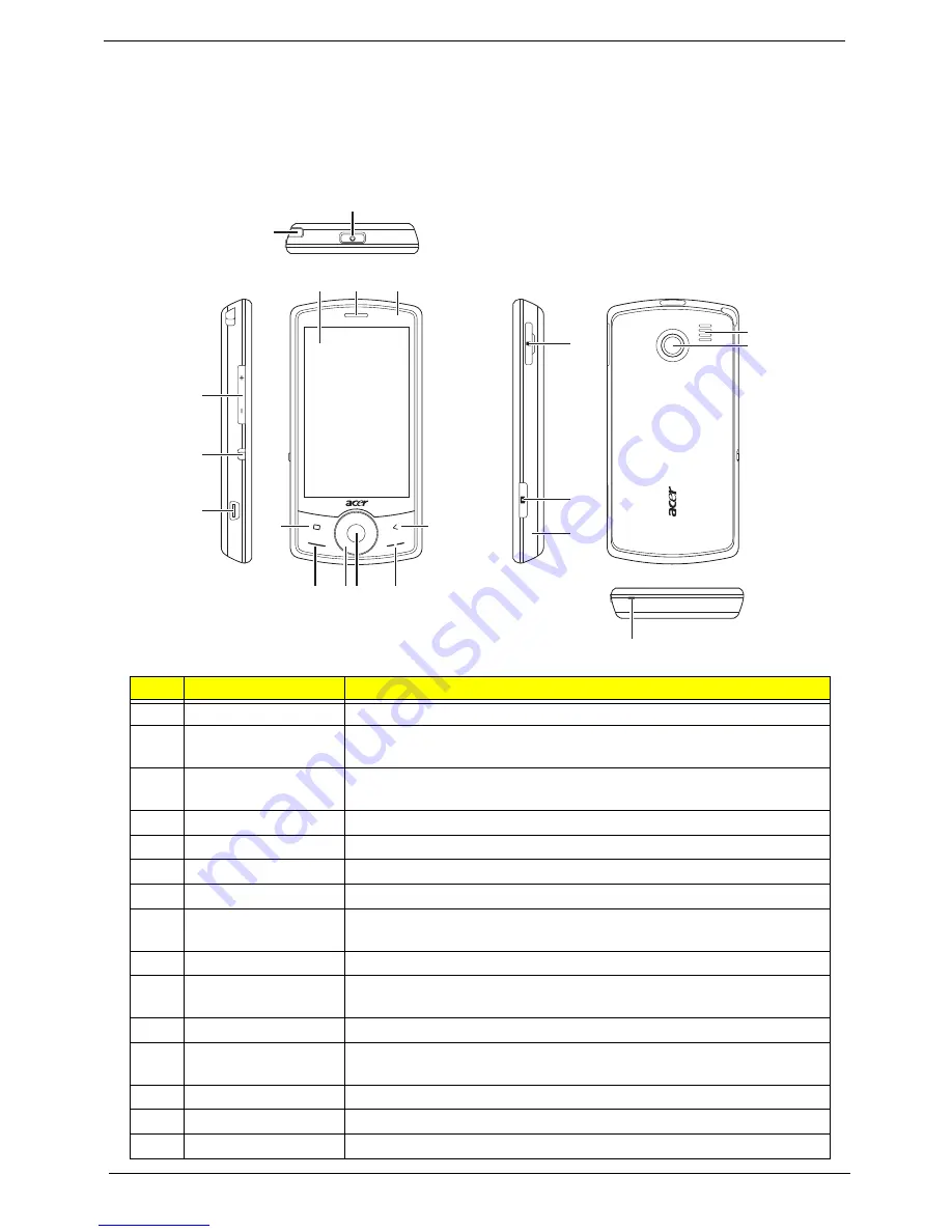
Your Acer Smartphone Tour

After examining your smartphone features, let us show you around your new smartphone.

Views

No.

Item

Description

1

Stylus 

Use to enter information or select items on the touch screen. 

2

Power button 

Press to turn the screen on/off or enter sleep mode; press and hold to 
turn the smartphone off. 

3

Touchscreen 

240 x 400 pixel screen to display data, phone content and enter 
information. 

4

Phone speaker 

Emits audio from your smartphone; suit-able for holding to your ear. 

5

LED Indicator

Indicates if the smartphone is powered on

6

Home button

Returns to the home screen

7

Call button 

Activate phone/dial/view recently dialed numbers/answer a call. 

8

Touch wheel/4-way 
button

Touch-sensitive wheel control with 4-way button

9

Center button

Use to select on-screen items

10

End button 

Press to end a call/disconnect GPRS; press and hold to turn the phone 
function on/off. 

11

Back Button

Go to the previous screen

12

Volume up / Volume 
down

Press to increase/reduce phone volume.

13

Silent button

Turns off speakers and turns on vibration module

14

Mini USB connector 

Connect to a USB cable/headphones/ charger. 

15

Microphone

Smartphone receiver / internal microphone

15

16

20

19

17

18

1

12

13

14

6

2

4

5

3

11

7 8 9

10


Summary of Contents for E101

Page 1: ...E101 Smartphone Service Guide PRINTED IN TAIWAN Service guide files and updates are available on the ACER CSD web for more information please refer to http csd acer com tw ...

Page 2: ...II Revision History Please refer to the table below for the updates made on the F900 smartphone service guide Date Chapter Updates ...

Page 3: ...r expressed or implied with respect to the contents hereof and specifically disclaims any warranties of merchantability or fitness for any particular purpose Any Acer Incorporated software described in this manual is sold or licensed as is Should the programs prove defective following their purchase the buyer and not Acer Incorporated its distributor or its dealer assumes the entire cost of all ne...

Page 4: ... bits and pieces of additional information related to the current topic WARNING Alerts you to any damage that might result from doing or not doing specific actions CAUTION Gives precautionary measures to avoid possible hardware or software problems IMPORTANT Reminds you to do specific actions relevant to the accomplishment of procedures ...

Page 5: ...generic service guide In such cases please contact your regional offices or the responsible personnel channel to provide you with further technical details 2 Please note WHEN ORDERING FRU PARTS that you should check the most up to date information available on your regional web or channel If for whatever reason a part number change is made it will not be noted in the printed Service Guide For ACER...

Page 6: ...VI ...

Page 7: ...the Mini SD Card 16 Removing the Battery Door 18 Removing the Battery 19 Removing the SIM Card 20 Main Unit Disassembly Process 21 Main Unit Disassembly Flowchart 21 Removing the Back Case 22 Removing the Vibration Module 26 Removing the Speaker 27 Removing the Side Buttons 28 Removing the Microphone Boot 31 Removing the SIM Daughter Board 32 Removing the Camera Shielding 33 Removing the Camera Mo...

Page 8: ...d 61 Replacing the Stylus 62 Diagnostics and Troubleshooting 63 Using the Diagnostic Utility 63 Installing the Diagnostic Utility 63 Running the Diagnostic Program 64 BT Phone Test 64 Key Test 66 Memory Test 67 LCM Test 67 BT Test 69 Speaker Test 69 Camera Test 70 Idle Current Test 71 Charge Current Test 72 RTC Battery Test 73 GPS Test 73 Reset 74 Using the Windows Mobile Test System 75 Serial Num...

Page 9: ...Display 240 x 400 TFT Liquid Crystal Display LCD with 18 bit color and LED back lighting and touch screen and 3 2 display Dimensions and Weight g including battery and stylus Communications Quad band GSM GPRS EDGE 850 900 1800 1900MHz Tri band UMTS 2100 1900 850MHz Dual band UMTS 2100 900MHz Modem EMP U365 POP Bluetooth Bluetooth 2 0 class 2 EDR Camera Built in 2 mega pixels camera up to 1600 x 12...

Page 10: ...y 1140mAh rechargeable Lithium Polymer Talk time Standby Pocket PC usage Software pre loaded Windows Mobile 6 1 Professional Microsoft Office Outlook Mobile Calendar Contacts Tasks and Inbox Microsoft Office Word Mobile Microsoft Office Excel Mobile Microsoft Office PowerPoint Mobile MSN Messenger Microsoft Transcriber Windows Media Player 10 Picture Notes Internet Explorer Mobile ActiveSync Calcu...

Page 11: ...SMS Sender MMS Composer SIM Manager Video Telephony Subject to change by region Multimedia Tools Image Maker Multimedia Manager Camera Camcorder Image Wizard FM Tuner Subject to change by region Utilities Quick Link Battery Meter Zoom SMS Bluetooth Manager M Desk Scenario Backup Utility Name card Manager GPS Tools Satellite Data Update Location SMS System Block Diagram ...

Page 12: ...tes if the smartphone is powered on 6 Home button Returns to the home screen 7 Call button Activate phone dial view recently dialed numbers answer a call 8 Touch wheel 4 way button Touch sensitive wheel control with 4 way button 9 Center button Use to select on screen items 10 End button Press to end a call disconnect GPRS press and hold to turn the phone function on off 11 Back Button Go to the p...

Page 13: ...re acceleration for faster Java based games and other applets Support for Bluetooth 2 0 EDR via external device High speed serial mobile display digital interface that optimizes Receive diversity support for WCDMA providing improved capacity and data throughput USB OTG core supports both slave and limited host functionality Built in high speed USB core and PHY Integrated wideband stereo codec for ...

Page 14: ...10 Lower 70 Item Specification Model 1 5 Inch System On A Chip SOC CMOS Digital Type Built in 2Mp resolution 1600H x 1200V Auto Focus CMOS camera up to 1600H x 1200V resolution Item Specification Type Bluetooth 2 0 EDR Interface UART and PCM Profiles Generic Serial FTP A2DP Headset Hands Free Item Specification Vendor model name Simplo US473850A8T Battery Type Li ion Polymer Rating 3 7 VDC Maximum...

Page 15: ...hold RESET after the logo screen appears 3 When the confirmation message appears press the camera button immediately to perform a clean boot Software Upgrade Procedure Using the Device Software Update Utility Before updating please ensure the PC being used to update has the following Windows XP SP2 or later versions Vista Windows 7 of the Windows operating system ActiveSync 4 5 or higher All firew...

Page 16: ...8 4 Execute the EUU executable file The Welcome screen displays 5 Click Next Specify a folder and permission ...

Page 17: ...9 6 Click Next The Confirm Installation screen displays 7 Click Next When EUU is installed the Completed screen displays ...

Page 18: ...ick Finish The Device Software Update Utility starts and the following screen displays 9 Follow the on screen instructions When the ActiveSync connection is established click Next The following screen displays ...

Page 19: ...11 10 Click Continue A warning screen displays 11 Click Yes A confirmation screen appears on the Smartphone 12 Click Yes A final confirmation screen appears on the PC ...

Page 20: ... begin the upgrade The Smartphone reboots to download mode and the following progress screens display on the Smartphone and PC The update is complete when the following screen displays 14 Click Close to exit the utility ...

Page 21: ...stic and metal NOTE The screws for the different components vary in size During the disassembly process group the screws with the corresponding components to avoid mismatch when putting back the components Related Information The product previews seen in the disassembly procedures may not represent the final product color or configuration General Information Pre disassembly Instructions IMPORTANT ...

Page 22: ... broken lines are optional and may not be present Screw Quantity Part No M 1 6X4 0 M WT NYLOK C 5 6052A0067302 I M 1 2X1 5 WT Ni GP 6 6052A0067402 5T M1 6X3 0 M BK Ni VER 02 GP 2 6052A0067502 Disconnect USB cable from system Remove Stylus Turn off system power Remove Battery Remove SIM Card Remove Back Cover Remove Mini SD Card ...

Page 23: ...Chapter 3 15 Removing the Stylus 1 Grasp the Stylus as shown and pull to remove it from the smartphone 2 Continue to pull the Stylus until it is completely removed from the smartphone ...

Page 24: ...and may not be present 1 Insert a finger nail or plastic pry into the casing and open the Mini SD door as shown 2 Pull the hinge out 1 and rotate the Mini SD door away from the card slot 2 as shown 3 Press the Mini SD card into the slot and release The card ejects automatically 1 2 ...

Page 25: ...Chapter 3 17 4 Remove the card from the slot and replace the Mini SD door ...

Page 26: ...tery Door IMPORTANT Cover the work area with a clean dry lint free cloth before placing the smartphone face down 1 Slide the Battery Door downwards until it disengages 2 Rotate the Battery Door away from the smartphone to remove it ...

Page 27: ...Chapter 3 19 Removing the Battery 1 See Removing the Battery Door on page 18 2 Push the Battery towards the top of the Smartphone as shown to release it 3 Lift the Battery out of the battery bay ...

Page 28: ...hapter 3 Removing the SIM Card NOTE The SIM Card is an optional item and may not be present 1 See Removing the Battery on page 19 2 Grasp the SIM Card as shown 3 Slide the SIM Card out of the slot as shown ...

Page 29: ...67402 SIM Daughter Board 5T M1 6X3 0 M BK Ni VER 02 GP 2 6052A0067502 Remove External Modules before proceeding Remove Mainboard Remove Vibration Module Remove Button Board Remove Camera Shielding Remove LCD Panel Remove Receiver Module Remove Back Cover Remove Speaker Module Remove Control Buttons Remove Keyboard Remove Microphone Boot Remove Sim Daughter Board Remove Camera Module Remove LED Gas...

Page 30: ...IMPORTANT Do not force the covers apart to avoid damaging the plastic securing clips IMPORTANT Use a plastic pry less than or equal to 0 96 mm thickness Metal tools may damage the covers 3 Starting at the left edge of the smartphone pry apart the covers Pull the inside of the battery recess out while pushing the Top Case with your thumb as shown to release the latches Step Screw Quantity Screw Typ...

Page 31: ...he top edge of the Smartphone clip circled below 5 Separate the bottom edge of the Smartphone using a pry tool as shown The securing clip is located in the center of the bottom edge 6 Separate the edges using a pry tool down the left side gradually prying apart the covers ...

Page 32: ...e cloth NOTE Take care when separating the covers The Silent Button is not attached to either cover and can easily fall out 9 The Back and Top Cases appear as shown below when separated IMPORTANT Be sure to note the condition of the water detection sticker A red sticker indicates that it has been directly exposed to water and the warranty may be void ...

Page 33: ...Chapter 3 25 10 Note the condition of the water detection sticker shown below The water detection sticker dissolves when in contact with water for an extended period ...

Page 34: ...ng the Vibration Module 1 See Removing the Back Case on page 22 2 Using the tweezers gently pry the Vibration Module loose of the Back Case 3 Grasp the rubber insulation and lift the Vibration Module out of the Back Case ...

Page 35: ...g the Back Case on page 22 2 Using the tweezers gently pry the Speaker loose of the Back Case The speaker is glued in place so care must be taken to remove not only the speaker but the glue below it as well 3 Lift the speaker away from the Back Case ...

Page 36: ...e Buttons 1 See Removing the Back Case on page 22 2 Grasp the Volume Button and lift it out of the Back Case 3 Grasp the Camera Button and lift it out of the Back Case 4 Push the Power Button in to release it from the securing tabs ...

Page 37: ...Chapter 3 29 5 Grasp the Power Button and lift it out of the Back Case 6 Grasp the Silent Button and lift it out of the Back Case 7 Grasp the outer ring of the Reset Button and slide it up along the pin ...

Page 38: ...30 Chapter 3 8 Lift the Reset Button out of the Back Case ...

Page 39: ...Chapter 3 31 Removing the Microphone Boot 1 See Removing the Back Case on page 22 2 Grasp the Microphone Boot and lift it out of the Back Case ...

Page 40: ... Board 1 See Removing the Vibration Module on page 26 2 Remove the two screws securing the SIM Daughter Board to the Mainboard 3 Lift the SIM Daughter Board away from the Mainboard as shown Step Screw Quantity Screw Type SIM Board M1 6 3 2 ...

Page 41: ... Removing the SIM Daughter Board on page 32 2 Insert thin tine tweezers under all four sides of the Shielding securing clips and gently pry the Shielding away from the Mainboard 3 Lift the Shielding clear of the Mainboard to expose the Camera Module ...

Page 42: ...elding on page 33 IMPORTANT use the camera removal tool shown below to replace the camera 2 Insert the camera removal tool into the camera well on the mainboard as shown until the clips on the outside edges disengage 3 Grasp the camera using the tool and pull straight up ...

Page 43: ...while gently pulling up the Mainboard 3 Pull up on the bottom right side of the mainboard to detach the connector to the Keyboard 4 Pull up on the edge of the mainboard to release it from the pin circled below 5 Slide the mainboard out from under the securing clip shown below Do not slide out completely or remove the mainboard at this time ...

Page 44: ... flip the assembly over 7 Lift the Top Case away from the Mainboard IMPORTANT Ensure that no dust dirt or finger prints come in to contact with the exposed LCD Module or Top Case Foreign particles and grease will affect LCD output performance If any prints or dust comes into contact with the LCD or cover use only water IPA Isopropyl Alcohol or Hexane and approved cleaning cloth ...

Page 45: ...ase will affect LCD output performance If any prints or dust comes into contact with the LCD use only water IPA Isopropyl Alcohol or Hexane and approved cleaning cloth 1 See Removing the Mainboard on page 35 2 Remove the tape securing the LCD FFC to the connector 3 Lift the FFC locking latch and disconnect the LCD FFC as shown 4 Lift the LCD Module away from the mainboard ...

Page 46: ... 3 Removing the Light Pipe Foam A small rubber gasket directs light from the power indicator LED to the top case 1 See Removing the Mainboard on page 35 2 Grasp the Light Pipe Foam and lift it out of the Top Case ...

Page 47: ... 3 39 Removing the Receiver Module 1 See Removing the Vibration Module on page 26 2 Pull the grounding tab up as shown 3 Pull the receiver module out to disengage the adhesive and lift it clear of the Top Case ...

Page 48: ... See Removing the Mainboard on page 35 2 Remove the tape securing the Touchscreen FFC to the connector 3 Remove the tape securing the Touchwheel FFC to the connector 4 Lift the FFC locking latch and disconnect the Touchscreen FFC as shown ...

Page 49: ...he Touchwheel FFC as shown 6 Lift the Touchwheel Board away from the Button Board and remove the six screws securing the Keyboard to the Top Case 7 Slide the Keyboard K B out from the slot in the Top Case Step Screw Quantity Screw Type Button Board M1 2 1 6 6 ...

Page 50: ...heel 1 See Removing the Keyboard on page 40 2 Push the two pins down into the holes as indicated 3 Slide the Touchwheel out from the Top Case IMPORTANT Take care when removing to not allow the Touchwheel Board to get snagged and torn ...

Page 51: ...Replacing Internal Module Components Replacing the Touchwheel 1 Slide the Touchwheel into the opening in the Top Case making sure the Touchwheel Board clears the opening 2 Push the Touchwheel onto the pins as shown ...

Page 52: ...lot in the Top Case and under the Touchwheel Board as shown 2 Insert the six screws to secure the Button Board to the Top Case 3 Insert the Touchwheel FFC into the connector and close the FFC locking latch as shown Step Screw Quantity Screw Type Button Board M1 2 1 6 6 ...

Page 53: ... Insert the Touchscreen FFC into the connector and close the FFC locking latch as shown IMPORTANT After closing only one of the two white lines on the FFC should be visible and should be flush with the edge of the locking mechanism 5 Adhere the tape to secure the Touchscreen FFC to the connector 6 Adhere the tape to secure the Touchwheel FFC to the connector ...

Page 54: ... Receiver Module 1 Remove backing tape from the adhesive on the new receiver module 2 Insert the receiver module into the receiver well in the Top Case 3 Bend the grounding tab over the edge of the well and pinch closed as shown ...

Page 55: ... the Top Case Replacing the LCD Module IMPORTANT Ensure that no dust dirt or finger prints come in to contact with the exposed LCD Module or Top Case Foreign particles and grease will affect LCD output performance If any prints or dust comes into contact with the LCD use only water IPA Isopropyl Alcohol or Hexane and approved cleaning cloth 1 Place the LCD Module onto the mainboard ...

Page 56: ...he LCD FFC and close the FFC locking latch as shown IMPORTANT After closing the white line on the FFC should be visible and flush with the edge of the locking mechanism 3 Adhere the tape to secure the LCD FFC to the connector ...

Page 57: ...Foreign particles and grease will affect LCD output performance If any prints or dust comes into contact with the LCD or cover use only water IPA Isopropyl Alcohol or Hexane and approved cleaning cloth 2 Holding the Top Case and Mainboard together flip the assembly over IMPORTANT The LCD Module is not secured to the Top Case or Mainboard Support the panel while turning the assembly over ...

Page 58: ...e the mainboard under the hook in the Top Case circled below 4 Press down on the base and right side to engage the hooks NOTE Check the four pins and screw holes to ensure the mainboard is seated properly in the Top Case ...

Page 59: ...al tool shown below to replace the camera 1 Grasp the camera using the camera removal tool note the position of the alignment pin it should align with the right side of the mainboard during insertion 2 Insert the Camera Module into the camera well on the mainboard as shown ...

Page 60: ...ielding over the camera 2 Push the edges of the Camera Shielding down to be sure that the securing clips on the shielding are engaged Replacing the SIM Daughter Board 1 Place the SIM Daughter Board D B onto the Mainboard as shown taking care to align the screw holes ...

Page 61: ...Daughter Board to engage the board to board connector 3 Insert the two screws to secure the SIM Board to the Mainboard Replacing the Microphone Boot 1 Insert the Microphone Boot into the well in the Back Case as shown Step Screw Quantity Screw Type SIM Board M1 6 3 2 ...

Page 62: ...54 Chapter 3 Replacing the Side Buttons 1 Insert the Volume Button into the Back Case 2 Insert the Camera Button into the Back Case 3 Insert the Power Button into the Back Case ...

Page 63: ...h the back of the Power Button in until the face is flush with the cover to engage the securing tab 5 Insert the Silent Button into the well as shown 6 Slide the Reset Button down along the pin until it rests at the base ...

Page 64: ...the Speaker 2 Insert the Speaker into the Back Case 3 Press the speaker module in place to engage the adhesive Replacing the Vibration Module 1 Grasping the Vibration Module firmly from both sides insert the Vibration Module into the vibration module well in the Back Case ...

Page 65: ... are flush with the well Replacing the Back Case 1 Align the silent button switch on the Mainboard with the Silent Button in the Back Case 2 Close the covers and press the right side together until the hooks snap into place taking care to keep the silent button aligned ...

Page 66: ...m and top of the covers together until the hooks snap into place 4 Slide the silent button up and down to make sure the button is aligned with the switch on the mainboard 5 Pinch the edges together above and below the silent button ...

Page 67: ...nwards while pressing the covers together until the back edge of the silent button snaps into place under the Back Case and the seam is flush 7 Replace the five screws located in the Back Case Step Screw Quantity Screw Type Top Case M1 6 4 5 ...

Page 68: ...60 Chapter 3 Replacing External Module Components Replacing the SIM Card 1 Slide the SIM Card into the SIM slot as shown Replacing the Battery 1 Insert the Battery into the battery bay ...

Page 69: ...apter 3 61 Replacing the Battery Door 1 Place the Battery Door into the smartphone 2 Push the Battery Door into place Replacing the Mini SD Card 1 Insert the card into the slot until it clicks into place ...

Page 70: ... 3 2 Rotate the Mini SD door towards the card slot as shown 3 Push the door into the case to secure it in place Replacing the Stylus 1 Push the stylus into the stylus holder in the top of the smartphone as shown ...

Page 71: ...oad the file 20090918DiagForC1 Ver 1 00 24 cab onto a micro SD card 3 Insert the micro SD card into the Smartphone 4 On the smartphone click Start File Explorer 5 Select Storage Card from the Show menu 6 Double click the file 20090918DiagForC1 Ver 1 00 24 cab to run it 7 Select to install on the device Chapter 4 ...

Page 72: ... Phone Test Before performing this test verify the following Pair a tested and functioning bluetooth headset to the smartphone 1 Open the file explorer 2 Browse to the diag folder 3 Double click the DiagMain application 4 Select the diagnostic utility to run See the following sections for detailed instructions ...

Page 73: ...Open the diagnostic utility 2 Select BT_Phone test 3 Click RUN 4 Click 2 The phone function activates 5 Make a phone call 6 If the phone call works properly and the headset can be used to communicate click Ok If the bluetooth headset does not work properly click NG ...

Page 74: ... for example click the Home button when Home is highlighted blue the camera button when CAM is highlighted blue etc The smartphone vibrates briefly if the button is pressed and functions correctly and the on screen button turns black If pressing a button results in no vibration note the button and click NG 4 Continue pressing buttons as directed by the on screen display until the test is complete ...

Page 75: ...Chapter 4 67 Memory Test LCM Test 1 Open the diagnostic utility 2 Select Mem_TF_Cal test 3 Note the information provided on screen 1 Open the diagnostic utility 2 Select LCM_LED test ...

Page 76: ...apter 4 3 Drag the slider across screen and verify that the backlight dims to 0 4 Examine the screen for any pixels that are black or off color Drag the stylus from left to right to switch to the next color ...

Page 77: ... 1 Open the diagnostic utility 2 Select BT Test and click RUN The test runs automatically and the result is displayed on screen 1 Open the diagnostic utility 2 Select Loopback Test and click RUN 3 Listen to make sure the MP3 is playing ...

Page 78: ...he camera button again to take a picture 3 Select the video button 4 Press the camera button to take a short video 5 Press the camera button again to stop recording 6 7 Click the camera browser button 8 Play the video recording and verify that it has saved properly 9 Browse to the pictures folder ...

Page 79: ...and verify that there are no dead pixels in the camera CMOS 1 Open the diagnostic utility 2 Select Idle Current Test and click RUN The screen will go blank as the phone idles 3 Briefly press the power button to bring the smartphone out of idle 4 Click Ok if the idle current test succeeds in putting the phone into idle ...

Page 80: ... the smartphone into the supplied charger before performing this test 1 Open the diagnostic utility 2 Select Charge Current Test and click RUN 3 Note the charge test results and click OK Click NG if External Power is N A while the phone is plugged into the charger ...

Page 81: ...least 1 minute for signal acquisition before determining that the GPS is faulty 1 Open the diagnostic utility 2 Select Rtc_Backupbattery and click RUN 3 the diagnostic utility runs the test and returns to the main screen with Ok or NG displayed in the test results column 1 Open the diagnostic utility 2 Select GPS Test and click RUN 3 Click OK at the prompt to go into QOS mode ...

Page 82: ...to rerun the tests click Reset 4 Wait until a signal is acquired The diagnostic returns to the main screen as soon as a position is calculated and displays OK in the status column 1 Open the diagnostic utility 2 Select Reset and click RUN The diagnostic program closes and clears all stored values ...

Page 83: ...cute Internet Explore to check if the Wireless LAN works well Must be able to open a website NOTE For problems related to Firewall and using Proxy please contact your IT specialists GPS Test 1 Execute the application as GPS Viewer 2 Check the contents of application Satellite searching status 1 No time limitation 2 Fix 3D Fixed Power Consumption Test Tools Dummy battery Power consumption program 2...

Page 84: ...76 Chapter 4 ...

Page 85: ...shown below The following describes the information on the product sticker Acer 22 Barcode Follows Code 128 standard refer to http www adams1 com pub russadam 128code html Acer_22_Code_SN PPPPPPPPPPYWWSSSSSMMVV Code Description PPPPPPPPPP Acer Part Number YWW 3 digit numeric year and week code SSSSS 5 character unique hexadecimal code by manufacturer base and reset each week 0 9 A B C D E F 16 cod...

Page 86: ...ion YWW 3 digit numeric year and week code as above dddddd 6 digit unique number derived from Acer 22 Code SN SSSSS Transfer Rule S1S2S3S4S5 dddddd S1 164 S2 163 S3 162 S4 16 S5 For example 001FD 000509 1 162 15 16 13 MM Manufacturer code as above Code Description ...

Page 87: ...ever reasons a part number change is made it will not be noted on the printed Service Guide For ACER AUTHORIZED SERVICE PROVIDERS your Acer office may have a DIFFERENT part number code from those given in the FRU list of this printed Service Guide You MUST use the local FRU list provided by your regional Acer office to order FRU parts for repair and service of customer machines NOTE To scrap or to...

Page 88: ...oam 3 Receiver 4 LCD Module LK 0320B 001 5 Mainboard 6 Camera Shield 7 Vibration Module 8 Speaker 9 Stylus 10 Power Button 11 Back Case 12 Battery Door 13 Main Key 14 K B PCB 15 Mic Holder 16 Daughter Board 17 Silence Button 18 Camera Button 19 Reset Button 1 2 3 4 5 6 7 8 9 10 11 12 13 14 15 16 17 18 19 ...

Page 89: ...BATTERY BT 00107 004 STYLUS WHITE STYLUS BLACK Adpt AP 0050P 008 Plug EU AP 0050P 002 Plug UK AP 0050P 003 Plug AU AP 0050P 005 Plug US AP 0050P 004 Plug CN AP 0050P 006 HEADSET KJAG4028AEUCB 3 M900 MAIN BOARD M B E1 with camera M B E1 w o camera K B SET K B SET D B SET D B SET TOP CASE SET ...

Page 90: ...TTOM CASE SET BLACK BOTTOM CASE SET WHITE BOTTOM CASE SET BLACK US BOTTOM CASE SET WHITE US RECEIVER SET RECEIVER SET SPEAKER SET SPEAKER SET BATTERY DOOR SET BATTERY DOOR SET WHITE BATTERY DOOR SET BLACK LCD LCD ASSY LK 0320B 001 ME PARTS CATEGORY PARTNAME ACER PART NO ...

Page 91: ...PER Black VOLUME KEY Black VOLUME KEY White POWER KEY White POWER KEY Black RESET KEY Black RESET KEY White CAMERA KEY Black CAMERA KEY White SILENT BUTTON Black SILENT BUTTON White MIC HOLDER MOTOR OPTICAL DEVICE CAMERA QM 02M04 001 SCREW SCREW I 12 15 M WT Ni VER 02 GP CATEGORY PARTNAME ACER PART NO ...

Page 92: ...VER 02 GP SCREW C 16 40 M WT NYLOK VER 02 Water Label LABEL WATER ZW6054A 01 GP IDA Label LABEL ZW6054A 01 IDA GP IMEI Label EN LABEL IMEI ZW6054A 01 ENG BOX GP IMEI Label TC LABEL IMEI ZW6054A 01 ENG BOX GP CATEGORY PARTNAME ACER PART NO ...

Page 93: ...ou can download information on all of Acer s products including Service guides for all models User s manuals Training materials Software utilities Spare parts lists TABs Technical Announcement Bulletin For these purposes we have included an Acrobat File to facilitate the problem free downloading of our technical material Also contained on this website are Detailed information on Acer s Internation...

Page 94: ...86 Appendix A ...

Page 95: ... Features 1 FRU Field Replaceable Unit List 79 K Keyboard Removing 40 L LCD Module Removing 37 Replacing 47 Light Pipe Foam Removing 38 Replacing 47 M Main Unit Disassembly Flowchart 21 Mainboard Removing 35 Replacing 49 Mic Cover Removing 31 Replacing 53 Microphone Boot Removing 31 Replacing 53 Mini SD Card Removing 16 Replacing 61 R Receiver Module Removing 39 Replacing 46 S SIM Board Removing 3...

Page 96: ...88 Replacing 43 V Vibration Module Removing 26 Replacing 56 Views 4 ...

Reviews: