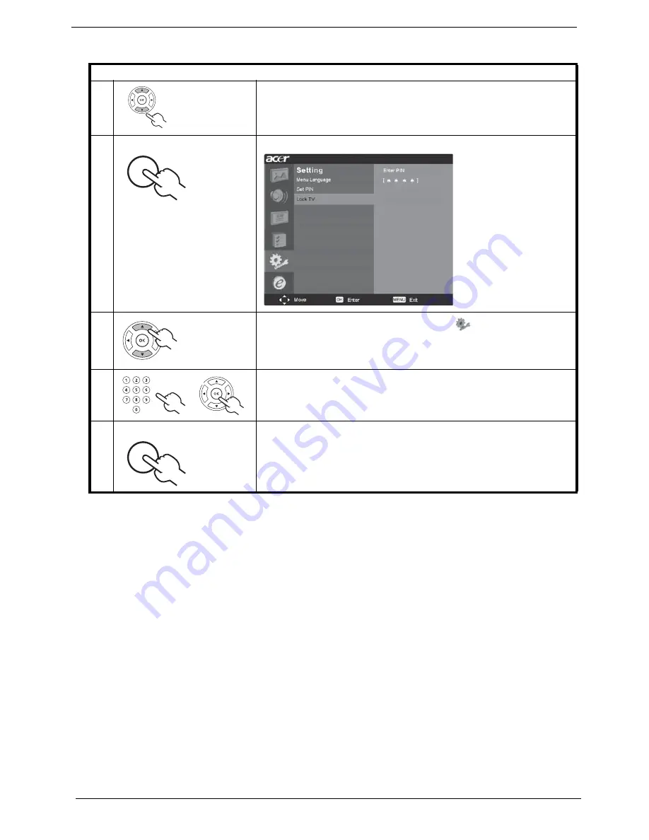
background image

26

Chapter 1

Locking your TV

1

Navigate to the channel you wish to manage.

2

Press the 

MENU

 key on the remote control to bring up the OSD.

3

Use the 

directional keys

 to navigate to the 

 Settings menu. Then 

select 

Lock TV

.

4

Enter a four-digit password. Type it again and press 

OK

 to reconfirm.

5

Press 

MENU

 to exit.

0(18

0(18

0(18

Summary of Contents for AT2703

Page 1: ...AT2703 Service Guide PRINTED IN TAIWAN Service guide files and updates are available on the AIPG CSD web for more information please refer to http csd acer com tw ...

Page 2: ...II Revision History Please refer to the table below for the updates made on AT2703 service guide Date Chapter Updates ...

Page 3: ...r expressed or implied with respect to the contents hereof and specifically disclaims any warranties of merchantability or fitness for any particular purpose Any Acer Incorporated software described in this manual is sold or licensed as is Should the programs prove defective following their purchase the buyer and not Acer Incorporated its distributor or its dealer assumes the entire cost of all ne...

Page 4: ... bits and pieces of additional information related to the current topic WARNING Alerts you to any damage that might result from doing or not doing specific actions CAUTION Gives precautionary measures to avoid possible hardware or software problems IMPORTANT Reminds you to do specific actions relevant to the accomplishment of procedures ...

Page 5: ... NOT be covered in this generic service guide In such cases please contact your regional offices or the responsible personnel channel to provide you with further technical details 2 Please note WHEN ORDERING FRU PARTS that you should check the most up to date information available on your regional web or channel If for whatever reason a part number change is made it will not be noted in the printe...

Page 6: ...A 8 Remote Control for EMEA 9 Remote Control for non EMEA 11 Basic Connection 12 OSD Navigation 16 Empowering Technology 19 Advanced Features 22 Dimensions 29 Source Options 30 Chapter3 Machine Disassembly and Replacement 31 General Information 32 Disassembly Procedure 33 Chapter4 Troubleshooting 41 Chapter6 FRU Field Replaceable Unit List 51 Exploded Diagram 52 Parts 54 ...

Page 7: ...TV input 3 5 mm earphone jack for audio line input Video functions Support PAL NTSC SECAM video format Support 480i 576i 480p 576p 1080i and 720p format Built in teletext functions Built in dynamic adaptive smoothing filter Built in dynamic temporal frame filtering noise reduction Built in dynamic motion and edge adaptive de interlacing Film mode 3 2 2 2 pull down Screen display model 16 9 4 3 pan...

Page 8: ...erating temperature 0 o C to 35 o C Operating humidity 10 to 90 non condensing Storage temperature 20 o C to 60 o C Shipping temperature 20 oC to 60 oC Storage humidity 10 to 90 non condensing Shipping humidity 10 to 90 non condensing Others On screen display adjustment function ISP In System Programming function available for revising driver easily ...

Page 9: ... 854 x 527 x 207 Weight Kg lbs 15 5 34 2 Gross Weight Kg lbs 16 5 36 4 Wall Mounting mm 200 x 100 Analog TV system TV color system PAL SECAM Sound system B G D K I L multi European Stereo system NICAM A2 TV Tuner system PLL 45 25MHz 862 25MHz Subtitles Teletext 1 5 Analog TV tuner quantity One Terminal Analog Tuner In Yes SCART1 CVBS In Out RGB In AudioR L SCART2 CVBS In Out RGB In AudioR L AV3 in...

Page 10: ...4 Chapter 1 Block Diagram System Block Wiring Diagram I O Board Scart RGB Scart RGB Tuner SPEAKER L IR power button Bd Key Earphone Board SPEAKER R INVERTER PANEL Board POWER MAIN Board ...

Page 11: ...Audio SW 744052 TA1218 AV Switch AV1 AV2 S1 S2 R G B H V TUNER AV S Video Video Switch 743257 YPbPr1 SCART1 YPbPr2 SCART2 SCART RGB AV2 S2 R L AV1 S1 R L TUNER SIF AV3 YPbPr R L SIF MB R L AUDIO Signal PC IN R L YPbPr3 YPbPr AV3 AV3 IO R L IO R L Button IR LVDS Audio Switch YPbPr2 R L YPbPr1 R L HDMI SiI9011 HDMI R L I2S D A Audio HDMI IN0 to PW328 option ...

Page 12: ...on functions the same as the Right arrow Volume down When the OSD is on functions the same as the Left arrow 2 Input key When the OSD is on press this button to confirm selection 3 Menu key Turns the OSD menu On and Off 4 Channel up When the OSD is on functions the same as the Up arrow Channel down When the OSD is on functions the same as the down arrow 386 32 5 ...

Page 13: ...er switch For AV3 Composite and component inputs share the same audio port HDMI only for AT2604 AT2704 AT3204 AT3704 DVI only for AT2604 AT2703 AT2704 AT3204 AT3704 2 AC in 3 HDMI in 4 VGA in 5 DVI in 6 Audio in 7 AV in 8 SCART x 2 9 Analog antenna in 7 7 7 7 7 7 7 ...

Page 14: ...uts share the same audio port HDMI only for AT2604 AT2704 AT3204 AT3704 DVI only for AT2604 AT2703 AT2704 AT3204 AT3704 2 AC in 3 HDMI in 4 VGA in 5 DVI in 6 Audio in 7 Component 1 2 in 8 AV 1 2 in 9 Analog antenna in 9 9 6 9 2 20321 17 20321 17 9 9 6 9 2 20321 17 20321 17 9 9 6 9 2 20321 17 20321 17 7 7 7 7 7 7 7 ...

Page 15: ...e the displayed picture 11 DISPLAY Press to display input channel information dependent on input source type 12 WIDE Press to toggle scaling mode between 4 3 16 9 Panorama and Letterbox 1 2 3 13 MENU Press to open or close the Menu 14 e Empowering technology Activate Acer Empowering Technology 15 Directional keys OK 16 MPX Press to select the sound input displayed in the top right hand corner mono...

Page 16: ...s to switch from TV AV to Teletext mode 5 SIZE Press once to zoom teletext page to 2X Press again to resume 6 MIX Press to overlay teletext page on the TV image 7 HOLD Press to pause the current teletext page in multi page viewing mode 8 SUBPAGE Press to access the teletext s subpages directly 9 Colour buttons R G Y B Operates corresponding button on the teletext page ...

Page 17: ...ggle scaling mode between 4 3 16 9 Panorama and Letterbox 1 2 3 12 MENU Press to open or close the Menu 13 e Empowering technology Activate Acer Empowering Technology 14 Directional keys OK 15 MTS Press to select the sound input information is displayed in the top right hand corner main stereo SAP 16 PIP PBP POP Switch between PIP PBP POP modes 17 SWAP For PIP PBP mode toggle between the primary a...

Page 18: ...k of the set 2 Connect the plug to the wall outlet as shown The power cord supplied varies according to your region Connecting an Antenna Cable Connect the antenna cable to the appropriate antenna terminal on the back of the TV set as shown below For EMEA For non EMEA QDORJ 9 9 6 9 2 20321 17 20321 17 QDORJ ...

Page 19: ...y for connection 1 HDMI 2 DVI 3 Component 2 SCART 3 Composite HDMI only for AT2604 AT2704 AT3204 AT3704 DVI only for AT2604 AT2703 AT2704 AT3204 AT3704 For non EMEA 5 5 5 5 8 2 20326 7 20321 17 6 57 9 9 RU 9 9 5 67 RU 0 6XE 9 6XE 9 9 HOORZ 5HG KLWH OXH UHHQ 5 9 9 20321 17 20321 17 6 9 2 5 5 20321 17 5 5 20321 17 LQ 8 2 5 5 8 2 6 6 9 2 6 9 LQ 20326 7 RU 9 9 5 67 RU 0 6XE 9 6XE 9 9 HOORZ 5HG KLWH OX...

Page 20: ...ebook computer to the TV as shown below NOTE For VGA and DVI input Acer recommends setting your PC s external monitor resolution to 1360 x 768 pixels 60Hz refresh rate DVI only for AT2604 AT2703 AT2704 AT3204 AT3704 Selecting the Input Source Once you have connected your antenna or external equipment to the TV you need to select the correct input source Press the corresponding button on the remote...

Page 21: ...ources 2 AV key Toggle AV3 and HDMI between input sources 3 COMPONENT key Toggle COMPONENT1 2 between input sources 4 PC key Toggle VGA and DVI between input sources NOTE HDMI only for AT2604 AT2704 AT3204 AT3704 DVI only for AT2604 AT2703 AT2704 AT3204 AT3704 ...

Page 22: ...ont panel view for details There are six main OSD menus These are Picture Audio Channel management Options Settings and Empowering Use the following method to navigate these menus 1 Press the MENU button on the remote control or the MENU button on the control panel 2 Select your desired menu by using the up and down directional keys to switch between the six menus 3 Use the directional keys to int...

Page 23: ...r down keys to adjust the sliding scale Press OK to save 4 The Audio menu can also be used to adjust the treble balance sound effects and other important sound related settings Adjusting the channel management 1 Press the MENU key to bring up the OSD 2 Using the directional keys select Channel management from the OSD 3 Use the directional keys to navigate the menus 4 The Channel management menu ca...

Page 24: ...18 Chapter 1 NOTE The options available on the OSD may vary depending on the TV signal source Some digital options may not be available with an analog signal and vice versa ...

Page 25: ...Empowering Key s default setting 1 Press and hold the Empowering Key for more than two seconds to open the menu The TV mode Empowering Key settings menu will come out as below 2 Use the directional keys to navigate the menu and select the Empowering Technology icon 3 Press MENU to exit Now when you press the Empowering Key your chosen selection will be accessed 0 18 HIDXOW VHWWLQJ LQ GLIIHUHQW PRG...

Page 26: ...s is accomplished through optimal Gamma correction plus saturation brightness and contrast adjustments Movie mode makes the most of high definition movie sound tracks Game Game mode carefully details the exquisite graphics of modern video games providing lifelike entertainment while protecting your eyesight by adjusting brightness and contrast What s more Game mode provides a heightened audio expe...

Page 27: ...e control 2 Use the directional keys to navigate the menu and select the Empowering Technology icon 3 Navigate to a channel slot use CH up down or number key to change channel There are a total of five slots in which you can store TV programs Viewing the favorite channels On the remote control if you press the Empowering Key for less than one second the TV will toggle between the five stored TV ch...

Page 28: ...the Activate key to toggle between PIP screens 2 Press the TV AV SCART COMPONENT or PC keys number keys or CH up or down to change the content of the active screen 3 Press SWAP key to change the content between the primary and the subscreen 4 Press the POSITION key to select the location of the subscreens from the upper leftJupper rightJlower rightJlower left as shown in the image 5 Press the SIZE...

Page 29: ...ress the ACTIVE key to toggle between PBP screens 2 Press the TV AV SCART COMPONENT or PC keys number keys or CH up or down to change the content of the active screen 3 Press the SWAP key to change the content between the primary and the PBP screen POP 1 Press the ACTIVE key to toggle between POP screens 2 Press the number keys or CH up or down to change the TV channel on the active screen 3 Press...

Page 30: ...nter 6163 to reset Setting a personal PIN 1 Navigate to the channel you wish to manage 2 Press the MENU key on the remote control to bring up the OSD 3 Use the directional keys to navigate to the Settings menu Then select Set PIN 4 Enter a four digit password Type it again and press OK to reconfirm 5 Press MENU to exit 0 18 0 18 0 18 ...

Page 31: ...wish to manage 2 Press the MENU key on the remote control to bring up the OSD 3 Use the directional keys to navigate to the Channel management menu Then select Lock this channel 4 Enter you PIN Type it again and press OK to reconfirm 5 Press MENU to exit 0 18 0 18 0 18 ...

Page 32: ...ish to manage 2 Press the MENU key on the remote control to bring up the OSD 3 Use the directional keys to navigate to the Settings menu Then select Lock TV 4 Enter a four digit password Type it again and press OK to reconfirm 5 Press MENU to exit 0 18 0 18 0 18 ...

Page 33: ... scan for new channels please follow the steps below Scanning for channels Auto scan 1 Press the MENU key on the remote control to bring up the OSD 2 Use the directional keys to navigate and select Channel management 3 Highlight Auto Scan Then select Start and press OK to begin 4 Select OK and press MENU to exit 0 18 0 18 0 18 0 18 ...

Page 34: ...e the display between the four wide modes 4 3 For 4 3 standard pictures a side bar will appear on each side 16 9 In this mode the whole picture is stretched toward each side of the screen Panorama In this mode the picture is progressively stretched toward each side of the screen Letterbox 1 2 and 3 In this mode the picture is enlarged linearly to fit the screen The top and bottom portions of the p...

Page 35: ...Chapter 1 29 Dimensions NOTE Unit mm 3 86 3 2 5 ...

Page 36: ...30 Chapter 1 Source Options 3 3 3 3 0DLQ 6XE 79 6 57 6 57 9 9 79 6 57 6 57 9 9 323 0DLQ 6XE 79 6 57 6 57 9 9 79 6 57 6 57 9 9 ...

Page 37: ...nd conductive mat for preventing electrostatic discharge T Small Philips screw driver T Philips screw driver NOTE The screws for the different components vary in size During the disassembly process group the screws with the corresponding components to avoid mismatch when putting back the components When you remove the stripe cover please be careful not to scrape the cover Machine Disassembly and R...

Page 38: ... 2 Unplug the AC adapter and all power and signal cables from the system NOTE There are several types of screws used to secure the product The screws vary in length Please group the same type of screws together during the disassembly process as well as remember the screw location for each screw type If you fasten the screws to the wrong location the screws may cause damage to the product ...

Page 39: ...oving the TV Stand 1 Release the four screws fastening the TV stand 2 Then pull out the TV stand Removing the I O Cover 1 Release those screws marked in yellow for removing the I O cover 2 Slide the I O cover shown as arrows then detach it ...

Page 40: ...the Rear Cover 1 Release those screws as shown for removing the rear cover 2 Then lift the rear cover Removing the ESD Shield Top 1 Release the nine screws securing the ESD shield top 2 Then lift the ESD shield top as shown ...

Page 41: ...he speakers to main board cable 4 Disconnect the LVDS to main board cable 5 Disconnect the inverter board to main board cable 6 Disconnect the power board to main board cable 7 Disconnect the other power board to main board cable 8 Disconnect the power switch to main board cable 9 Release the ten screws fastening the main board and the I O board 10 Remove them together then separate them ...

Page 42: ...36 Chapter 2 ...

Page 43: ...Chapter 2 37 Removing the Power Supply Board 1 Release the seven screws fastening the power supply board and the cable then detach the power supply board ...

Page 44: ...38 Chapter 2 Removing the PCD Holder 1 Release those screws marked in yellow 2 Then lift the PCD holder as shown ...

Page 45: ... Power Button Board 1 Release the five screws fastening the keypad board then detach it 2 Release the four screws fastening the power button board then detach it 3 They are the keypad board and the power button board with their corresponding cables ...

Page 46: ...2 Removing the LCD 1 Release the four screws on the LCD brackets 2 Then lift the LCD Removing the Speakers 1 Release the four screws securing the speaker 2 Repeat the anterior two steps to remove the other speaker ...

Page 47: ...create the failure running the diagnostic tests or repeating the same operation 3 Disassemble and assemble the unit without any power sources 4 If any problem occurs you can perform visual inspection before you fellow this chapter s instructions You can check the following 1 Power cords are properly connected and secured 2 There are no obvious shorts or opens 3 There are no obviously burned or hea...

Page 48: ...Power on No power on No 1 LCD Fail 2 4 10 7 5 3 Remote Control Fail DDC POP PIP Fail RF No Signal HDTV Fail TV Channel Fail Unit Hang Up Suddenly AV1 AV2 AV3 Speaker No Sound Can t Change to Factory Mode Button Function Fail 9 8 6 Yes ...

Page 49: ...Chapter 3 43 1 Power Cord Power Cable Power Board Main Bard END Replacement Replacement Replacement Replacement N G N G N G N G ...

Page 50: ...hapter 3 2 LCD No Back Light LCD No Display CCFT Cable Inverter Board LCD Panel Main Board END END LCD Panel Main Board LCD Cable Replacement Replacement Replacement Replacement N G N G N G N G N G N G N G ...

Page 51: ...Chapter 3 45 3 Button Board I O Board Main Board END Replacement Replacement Replacement N G N G N G ...

Page 52: ...46 Chapter 3 4 Main Board END Replacement N G 5 IR Cable IR board Main Board END Replacement Replacement Replacement N G N G N G ...

Page 53: ...Chapter 3 47 6 IO Board Main Board END Replacement Replacement N G N G 7 Button Cable Button Board Main Board END Replacement Replacement Replacement N G N G N G ...

Page 54: ...48 Chapter 3 8 Power Board Main Board END Replacement Replacement N G N G ...

Page 55: ...Chapter 3 49 9 Speck Cable Speaker Head phone Cable Main Board IO Board END Replacement Replacement Replacement Replacement Replacement N G N G N G N G N G ...

Page 56: ...50 Chapter 3 10 Button Cable Button Board IO Board Main Bard END Replacement Replacement Replacement Replacement N G N G N G N G ...

Page 57: ...is changed it will NOT be noted on the printed service guide For Acer authorized service providers your Acer office may have a different part number code from those given in the FRU list of this printed service guide You MUST use the local FRU list provided by your regional Acer office to order FRU parts for service NOTE To scrap or to return the defective parts you should follow the local governm...

Page 58: ...52 Chapter 4 Exploded Diagram ...

Page 59: ...17 Shield down 18 Cable GND GND 19 Cable IB GND 20 Cable INV CML 21 Cable LVDS 22 Cable speaker 23 Cable MB AV3 24 Cable key IR 25 Cable MB PWR 26 PW audio 27 Screw T3 B P black 28 Screw T3 0 10 0 P NI 29 Screw T3 12 B NI EP 30 Screw M4 0 4 I NYLOK 31 Screw M3 0 3 P BK 32 Screw T4 12 B Black 33 Screw M3 6 B BNI 34 Screw M4 6 P MC 35 Screw M4 12 P MC 36 IO nut 37 Gasket RS 38 Gasket TOP 39 Label IO...

Page 60: ...54 Chapter 4 Parts The latest parts information will be updated shortly ...

Reviews: