2-10
System Utilities
Changing a Password
0
1. Use the
and
keys to highlight Set Supervisor Password and press the
Enter
. The Set
Supervisor Password box appears.
Figure 2-6.
Set Supervisor Password
2. Type the current password in the
Enter Current Password
field and press
Enter
.
3. Type a password in the
Enter New Password
field. Retype the password in the
Confirm
New Password
field.
Figure 2-7.
Setup Notice
4. Press
Enter
. The computer sets User Password parameter to Set.
NOTE:
NOTE
:
Users can enable the Password on boot parameter.
5. Press
F10
to save changes and exit the BIOS Setup Utility.
If the verification is OK, the screen will show as following.
Figure 2-8.
This Setup Warning
The password setting is complete after the user presses
Enter
.
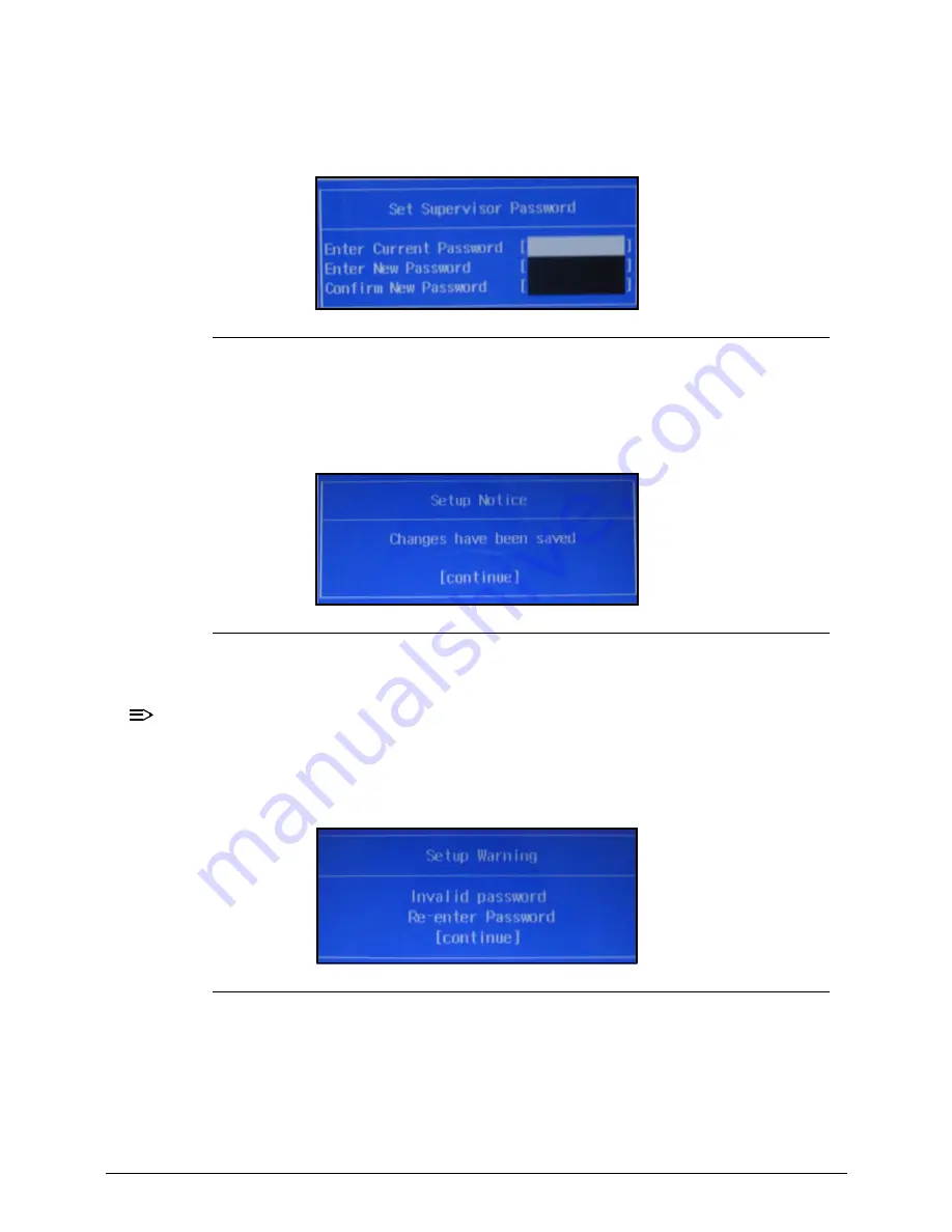
If the current password entered does not match the actual current password, the screen will
show the Setup Warning (Figure 2-9).
Summary of Contents for Aspire M3-581T
Page 1: ...Acer M3 581T 581TG SERVICEGUIDE...
Page 4: ...iv...
Page 9: ...v...
Page 10: ...vi...
Page 11: ...CHAPTER 1 Hardware Specifications...
Page 14: ...1 4...
Page 32: ...1 22 Hardware Specifications and Configurations System Block Diagram...
Page 50: ...1 40 Hardware Specifications and Configurations...
Page 51: ...CHAPTER 2 System Utilities...
Page 61: ...System Utilities 2 11 Figure 2 9 Setup Warning...
Page 83: ...System Utilities 2 33 13 Key in q to exit Broadcom program Figure 2 37 Exit Broadcom program...
Page 84: ...2 34 System Utilities...
Page 85: ...CHAPTER 3 Machine Maintenance...
Page 88: ...3 4...
Page 99: ...3 15 3 Pull the WLAN module out and away Figure 3 14 WLAN Module...
Page 102: ...3 18 5 Pry the ODD bezel off the ODD module Figure 3 19 ODD Bezel...
Page 109: ...3 25 11 Remove the keyboard from the top case Figure 3 31 Keyboard module...
Page 112: ...3 28 Figure 3 37 Battery module...
Page 121: ...3 37 3 Lift the thermal module and take it away Figure 3 54 Thermal Module...
Page 124: ...3 40 3 Remove the speakers and cable Figure 3 58 Speakers...
Page 129: ...3 45 Figure 3 67 LCD Bezel...
Page 137: ...3 53 Replacing the Bluetooth 0 1 Place the Bluetooth into the socket Figure 3 81 Bluetooth...
Page 167: ...CHAPTER 4 Troubleshooting...
Page 194: ...4 28 Troubleshooting...
Page 195: ...CHAPTER 5 Jumper and Connector Locations...
Page 203: ...CHAPTER 6 FRU List...
Page 222: ...6 20 FRU Field Replaceable Unit List...
Page 223: ...CHAPTER 7 Test Compatible Components...
Page 224: ...8 2 Microsoft Windows 7 Environment Test 7 4 M3 581T 581TG 7 4...
Page 230: ...7 8 Test Compatible Components...
Page 231: ...CHAPTER 8 Online Support Information...
Page 232: ...9 2 Introduction 8 3...
Page 234: ...8 4 Online Support Information...


