background image

47

Chapter 3

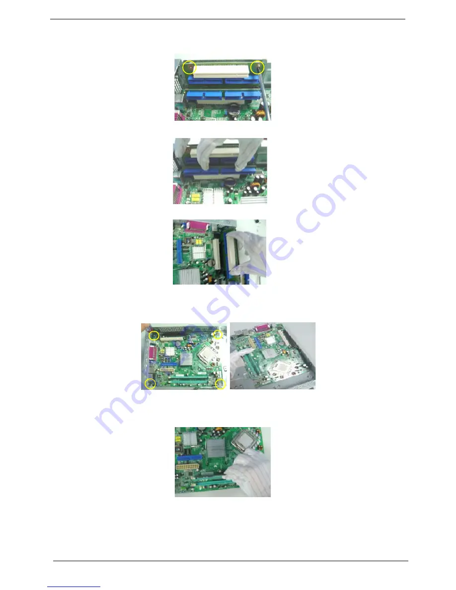
Removing the Riser Card

1.

Remove the two screws securing the PCI Express riser card.

2.

Remove the PCI riser card from the mainboard PCI slot.

3.

Remove the PCI express riser card from the mainboard PCI express slot.

Removing the Mainboard

1.

Remove the eight screws securing the mainboard and remove it.

Removing the Memory

1.

Loose the DIMM latch and pop out the memory as shown.


Summary of Contents for Aspire L300

Page 1: ...Aspire L300 Veriton 2800 Service Guide PRINTED IN TAIWAN Service guide files and updates are available on the AIPG CSD web for more information please refer to http csd acer com tw ...

Page 2: ...4 Revision History Please refer to the table below for the updates made on Aspire L300 Veriton 2800 service guide Date Chapter Updates 8 30 2005 First release ...

Page 3: ...spect to the contents hereof and specifically disclaims any warranties of merchantability or fitness for any particular purpose Any Acer Incorporated software described in this manual is sold or licensed as is Should the programs prove defective following their purchase the buyer and not Acer Incorporated its distributor or its dealer assumes the entire cost of all necessary servicing repair and a...

Page 4: ... bits and pieces of additional information related to the current topic WARNING Alerts you to any damage that might result from doing or not doing specific actions CAUTION Gives precautionary measures to avoid possible hardware or software problems IMPORTANT Reminds you to do specific actions relevant to the accomplishment of procedures ...

Page 5: ... NOT be covered in this generic service guide In such cases please contact your regional offices or the responsible personnel channel to provide you with further technical details 2 Please note WHEN ORDERING FRU PARTS that you should check the most up to date information available on your regional web or channel If for whatever reason a part number change is made it will not be noted in the printe...

Page 6: ...ures 26 Integrated Peripherals 27 Power Management Setup 31 PnP PCI Configuration 33 PC Health Status 34 Frequency Control 35 Load Optimized Defaults 36 Set Supervisor User Password 37 Save Exit Setup 38 Exit Without Saving 39 Chapter 3 Machine Disassembly and Replacement 40 General Information 41 Disassembly Procedure 42 Chapter 4 Troubleshooting 49 Power On Self Test POST 50 POST Error Messages ...

Page 7: ...2 ...

Page 8: ... 945G ICH7 Lakeport chipset architecture The combination can run at 800 1066 MHz FSB which gives more performance than other processors We also provide 1 PCI Express x16 slot for add on graphic solution 1 PCI Express x1 slot and 1 PCI slots support PCI 2 2 spec 2 dual channel DDR2 memory slots one parallel ATA port 2 serial ATA2 ports and on board Gigabit LAN on board Audio function Both of these ...

Page 9: ...o 667 MHz T Support dual channel function Graphic Solution T Intel Lakeport G on die graphic solution T DVMT technology support T Dual View function support T PCI E x16 VGA Add On Card Slots T 1 PCI Express x16 slot T 1 PCI 2 2 5V slot FDD T One 1 44MB 3 5 device PATA IDE T Slot Type 40pin PATA IDE slot T Slot Quantity 1 T Transfer rate support PIO mode 0 3 33MB s 1 5 22MB s 2 8 33MB s 3 11 1MB s ...

Page 10: ...ly T Support 1394a T One port on the back T One 2 5 internal header On Board Connector T Rear I O Connectors T 1 PS 2 Keyboard Port 1 PS 2 Mouse Port T 1 Parallel Port 1 Serial Port T 1 RJ45 GigaLAN Port T 1 VGA port T 4 USB Ports for P1 L 4 USB ports IEEE 1394 port for P1 C T 6 Ports Jack Support HD High Definition Audio Output 7 1 channel T On Board Connectors T 1 CPU Socket T 2 Memory Socket T ...

Page 11: ...onnector with linear circuit T 1 4 pin System FAN connectors with linear circuit T 1 intrusion alarm connector T 1 2pin LAN activity monitor connector T 1 Intrusion Alarm connector T 1 2 5 pin Intel FPIO specification power switch power state LED HDD active LED T 1 24pin 4pin ATX interface PS3 PS2 SPS connector T 1 reserved GPIO pin connector for one button recovery function T 2 reserved 2pin GPIO...

Page 12: ...ont Panel VRD 10 1 DIMM1 Back Panel Firmware HUB PS2 4 Phase PWM DIMM2 ATA100 Socket T USB2 0 Port 6 4Mb or 8Mb 4 Lanes USB2 0 Port 2 ICH7RW Keyboard Mouse CK 410 Clock DDR2 533 667 IDE CONN 1 PCI Express x1 Interface Direct Media Interface DMI Channel A DDR2 Super I O USB2 0 Port 3 GMCH PCI Slot 1 Lakeport DDR2 533 667 Realtek ALC880 8 Channels W SPDIF Out LPC I F USB2 0 Port 7 Header USB2 0 Port...

Page 13: ... Chapter 1 Aspire L300 Front Panel No Description No Description 1 Optical drive 2 Power button 3 Indicators 4 Microphone in jack 5 USB ports 6 Speaker Headphone jack 7 Media card reader 8 IEEE 1394 port ...

Page 14: ...Chapter 1 7 Veriton 2800 Front Panel No Description No Description 1 5 25 drive bay 2 3 5 drive bay 3 Microphone in jack front 4 Speaker out 5 USB ports 6 Indicator 7 Power button No Icon Component ...

Page 15: ...pire L300 Rear Panel No Description No Description 1 Power supply 2 Audio jack 3 USB ports 4 CRT LCD monitor port 5 Parallel printer port 6 Serial ports 7 PS 2 keyboard port 8 PS 2 mouse port 9 LAN port 10 1394 port ...

Page 16: ...scription 1 Power supply 2 Power cord socket 3 PS 2 mouse port 4 PS 2 keyboard port 5 Serial port 6 Parallel printer port 7 CRT LCD monitor port 8 USB ports 9 Network port 10 Audio jack 11 Expansion slot 12 Chassis lock pad 13 Hardware reset button omponent ...

Page 17: ...10 Chapter 1 Mainboard Layout ...

Page 18: ...r Mill LGA 775 processor Slot Socket T LGA 775 Speed Depends on CPU up to3 8 GHz Bus Frequency 533 800 1066 MHz Voltage Processor voltage can be detected by any system without setting any jumper BIOS Item Specification BIOS code programmer Award BIOS version R01 A4 BIOS ROM size 4MB BIOS ROM package 32 pin PLCC package Support protocol PCIX 1 0 PCI 2 2 APM 1 2 VESA DPMS VBE PM V1 1 SMBIOS 2 3 E ID...

Page 19: ...ations VRM Voltage Regulator Module Function VRM Specification Typical Voltage Power Source Maximum Output CPU VRM VRM10 1 0 8375 1 6v 12 Voltage 101A CPU VRM VRM 9 0 1 1 1 85 Voltage 12 Voltage 70A Cache Memory Item Specification First Level Cache Configurations Cache function control Enable Disable by BIOS Setup Second Level Cache Configurations The information below is only applicable to system...

Page 20: ... Device Type Support HDD CD ROM CD RW DVD ROM DVD RW DVD RW DVDDual DVD Supermultiplus Supports LS 120 Yes Supports bootable CD ROM Yes Function Control Enable Disable by BIOS setup Diskette Drive Interface Item Specification Diskette Drive Controller IT8712F Diskette Drive Controller Resident Bus LPC Bus Supported Diskette Drive Formats 1 44MB 2 88MB format and slim type diskette drive Function C...

Page 21: ...iption Thermal Design T Provision for optional secondary fan T Adequate venting in the front of chassis T Adequate venting in the rear of chassis Environmental Requirements Item Specifications Temperature Operating 5 C 35 C Non operating 20 60 C Storage packed 10 C 60 C un packed Humidity Operating 15 to 80 RH non condensing Non operating 10 to 90 RH non condensing at 40 C Vibration Operating unpa...

Page 22: ...ard Package Cross Weight Drop Height Not of Drop KGs lbs CM Inch 0 9 1 0 20 76 30 10 9 1 18 2 20 40 61 24 10 18 2 27 3 40 60 46 18 10 27 3 45 4 60 100 31 12 10 10 drops one corner three edges six surfaces Drop Test Drop Test ...

Page 23: ...switch button modem ring in keyboard and mouse for APM mode T Resume recovery time 7 10 sec Suspend Mode T Independent power management timer 2 120 minutes time step 10 minutes or pushing external switch button T CPU goes into SMM T CPU asserts STPCLK and goes into the Stop Grant State T LED on the panel turns amber colour T Hard disk drive goes into SLEEP mode for ATA standard interface T Disable...

Page 24: ... doesn t required users to boot to DOS before upgrading BIOS but directly download and update BIOS from the Internet NOTE Main Menu This is the online description of the highlighted setup functions is displayed at the bottom of the screen NOTE Status Page Setup Menu Option Page Setup Menu Press F1 to pop up a small help window that describes the appropriate keys to use and the possible selections ...

Page 25: ...nced option hidden As for the hidden options we have annotations following those with further setting screen menu Esc Quit KLIJ Select XPnP PCI Configurations Exit Without Saving Set Supervisor Password XIntegrated Peripherals Set User Password XPower Management Setup Save Exit Setup F10 Save Exit Setup Phoenix AwardBIOS CMOS Setup Utility XProduct Information XPC Health Status XStandard CMOS Feat...

Page 26: ... function features PnP PCI Configuration This setup page includes all configurations of PCI PnP ISA resources PC Health Status This setup page is the System auto detect Temperature voltage fan and speed Frequency Control This setup page includes all the items of Frequency Control Load Default Settings Default Settings indicates the value of the system parameters which the system would be in best p...

Page 27: ... BIOS version SMBIOS Version This item lists the system SMBIOS version System BIOS ID This item lists the system BIOS ID BIOS Release Date This item lists the BIOS release date Help Item System Product Name Vertion 2800 MB Product Name G945PL G945PC System Manufacture Name Acer MB Manufacture Name Acer System BIOS Version 6 00 PG F6 Load Optimized Defaults F7 Load Fail Safe Defaults Phoenix AwardB...

Page 28: ...annel 0 Slave None XIDE Channel 1 Master HL DT ST RW DVD GCC Extended Memory 252928K F6 Load Optimized Defaults F7 Load Fail Safe Defaults Halt On All But Keyboard Phoenix AwardBIOS CMOS Setup Utility Standard CMOS Features XIDE Channel 1 Slave None Video EGA VGA KLIJ Move Enter Select Value ESC Exit F1 General Help XTime HH MM SS 11 08 43 XIDE Channel 0 Master None ...

Page 29: ...Enter The IDE CD ROM is always automatically detected IDE HDD Auto Detection Press Enter to select this option for automatic device detection IDE Primary Secondary Master Slave IDE Device Setup You can use one of three methods Auto Allows BIOS to automatically detect IDE devices during POST default None Select this if no IDE devices are used and the system will skip the automatic detection step an...

Page 30: ...rs Whenever the BIOS detects a non fatal error the system will be stopped All But Keyboard The system boot will not stop for a keyboard error it will stop for all other errors Default value All But Diskette The system boot will not stop for a disk error it will stop for all other errors All But Disk Key The system boot will not stop for a keyboard or disk error it will stop for all other errors Pa...

Page 31: ...On Self Test Enabled APIC Mode Enabled F6 Load Optimized Defaults F7 Load Fail Safe Defaults Gate A20 Option Fast Third Boot Device Enabled Boot Other Device Disabled Boot Up NumLock Status On KLIJ Move Enter Select Value ESC Exit F1 General Help Security Option Setup Phoenix AwardBIOS CMOS Setup Utility Advanced BIOS Features Silent Boot Enabled First Boot Device Enabled Second Boot Device Enable...

Page 32: ...n Enabled Disabled First Second Third Boot Device The item allows you to set the sequence of boot device where BIOS attempts to load the disk operating system Floppy LS120 Hard Disk CD ROM ZIP USB FDD USB ZIP USB CDROM USB HDD LAN Disabled Boot other Devices This item allows you to enable or disable to boot from other device Enabled Disabled Boot Up NumLock Status This item allows you to enable or...

Page 33: ...e and Slow gives more stable performance This field applies only when synchronous DRAM is installed in the syste 2 3 4 5 6 Auto Precharge Delay This option is used to set up the timing delay between the SDRAM active to precharge 4 5 6 7 8 9 10 11 12 Auto On Chip Memory Size Select the on chip memory size for VGA drive use PEG Onchip VGA Control This option is used to control the VGA Onchip VGA PEG...

Page 34: ...ls X SuperIO Device Press Enter Help Item Menu Level X Phoenix AwardBIOS CMOS Setup Utility OnChip IDE Device IDE Primary Master PIO Auto IDE Primary Master UDMA Auto IDE Primary Slave UDMA Auto Help Item Menu Level X IDE DMA transfer access Enabled On Chip Primary PCI IDE Enabled IDE Primary Slave PIO Auto F6 Load Optimized Defaults F7 Load Fail Safe Defaults x PATA IDE Mode Primary On Chip Seria...

Page 35: ... Keyboard Support Enabled Azalia Select Auto Onboard 1394 Enabled Help Item Menu Level X USB Controller Enabled USB 2 0 Controller Enabled Phoenix AwardBIOS CMOS Setup Utility Super IO Device Onboard Parallel Port 378 IRQ7 x ECP Mode Use DMA 3 Help Item Menu Level X POWER ON Function BUTTON ONLY Onboard Serial Port 1 3F8 IRQ4 Parallel Port Mode PRINTER F6 Load Optimized Defaults F7 Load Fail Safe ...

Page 36: ...em if the system supports USB 2 0 Enabled Enable USB 2 0 Controller Disabled Disable USB 2 0 Controller USB Keyboard Support This item lets you enable or disable the USB keyboard driver within the onboard BIOS The keyboard driver is simulates legacy keyboard command and lets you use a USB keyboard during POST or after boot if you do not have a USB driver in the operating system Enabled Enable USB ...

Page 37: ...uto BIOS will automatically setup the port 1 or 2 address 3F8 IRQ4 Serial Port 1 default 2F8 IRQ3 Serial Port 2 default 3E8 IRQ4 2E8 IRQ3 Diabled Disable onboard Serial port 1 or 2 Parallel Port Mode This feature allows to select the Parallel Port Mode SPP EPP1 9 SPP ECP EPP1 9 ECP PRINTER EPP1 7 SPP EPP1 7 ECP Parameter Description Options ...

Page 38: ...ment Features Run VGABIOS if S3 Resume Auto CPU THRM Throttling 50 0 Wake Up by PCI card Disabled Help Item Menu Level X X PCI Express PM Function Press Enter Sleep Mode S3 STR PWRON After PWR Fail Former Sts F6 Load Optimized Defaults F7 Load Fail Safe Defaults x Date of Month Alarm 0 Power On by Ring Disabled USB KB Wake Up From S3 Disabled Resume by Alarm Disabled KLIJ Move Enter Select Value E...

Page 39: ... CPU THRM Throttling 25 0 37 5 50 0 62 5 75 0 87 5 Wake Up by PCI card This item allows the activity of the PCI devices to wake up the system from S3 sleep state Enabled Disabled Power On by Ring An input signal on the serial Ring indicator line in other words and incoming call on the modem awakens the system from a soft off state Enabled Disabled USB KB Wake Up From S3 This item allows user to en...

Page 40: ...manually IRQ Resource When resource are controlled by manually assign each system interrupt a type depending on the type of device using the interrupt PCI Device Assign this IRQ for PCI device Reserved Reserve this IRQ for other device PCI VGA Palette Snoop Enabled Enable PCI VGA Palette Snoop function Disabled Disable this function Phoenix AwardBIOS CMOS Setup Utility PNP PCI Configuration Resour...

Page 41: ... CPU System Temperature automatically CPU FAN Speed RPM Detect CPU Fan Speed status automatically Hidden Setting Shutdown Temperature 80 C 176 F 85 C 185 F 90 C 194 F 95 C 203 F Disabled Phoenix AwardBIOS CMOS Setup Utility PC Health Status Current System Temperature 45o C 113o F 12 0V 12 02 V 3 3V 3 23 V Help Item 5 V 5 01 V CPU Fan Speed 0 RPM F6 Load Optimized Defaults F7 Load Fail Safe Default...

Page 42: ...trum This feature allows to enable disable the Spread Spectrum modulate Enabled Disabled Phoenix Award BIOS Setup Utility Frequency Control Spread Spectrum Enabled Help Item Menu Level X CPUID Maximum Value Limit Disabled Auto Detect PCI Clk Enabled F6 Load Optimized Defaults F7 Load Fail Safe Defaults KLIJ Move Enter Select Value ESC Exit F1 General Help ...

Page 43: ...assword XAdvanced BIOS Features Load Optimized Defaults XAdvanced Chipset Features Load Optimized Default Y N Phoenix AwardBIOS CMOS Setup Utility XProduct Information XPC Health Status XStandard CMOS Features XFrequency Control Set Supervisor Password XPower Management Setup Save Exit Setup Esc Quit KLIJ Select XPnP PCI Configurations Exit Without Saving F10 Save Exit Setup ...

Page 44: ...can be used to start the system or modify the CMOS settings The User password can also start the system While the User password XIntegrated Periphera Password XAdvanced BIOS Features Load Optimized Defaults XAdvanced Chipset Features Enter Password Phoenix AwardBIOS CMOS Setup Utility XProduct Information XPC Health Status XStandard CMOS Features XFrequency Control Set Supervisor Password XPower M...

Page 45: ...ess N to return to the main menu XIntegrated Periphera Save to CMOS and Exit Y N N XAdvanced BIOS Features Load Optimized Defaults XAdvanced Chipset Features Set Supervisor Password Phoenix AwardBIOS CMOS Setup Utility XProduct Information XPC Health Status XStandard CMOS Features XFrequency Control XPower Management Setup Save Exit Setup Esc Quit KLIJ Select XPnP PCI Configurations Exit Without S...

Page 46: ...s that you do not want to save use the Exit Without Saving item and press Y to discard any changes you have made XIntegrated Periphera Password XAdvanced BIOS Features Load Optimized Defaults XAdvanced Chipset Features Quit Without Saving Y N Y Set Supervisor Password Phoenix AwardBIOS CMOS Setup Utility XProduct Information XPC Health Status XStandard CMOS Features XFrequency Control XPower Manag...

Page 47: ...nding strap and conductive mat for preventing electrostatic discharge T Wire cutter T Phillips screwdriver may require different size NOTE The screws for the different components vary in size During the disassembly process group the screws with the corresponding components to avoid mismatches when putting back the components Machine Disassembly and Replacement Chapter 3 ...

Page 48: ...on Before You Begin Before proceeding with the disassenbly procedure make sure that you do the following 1 Turn off the power to the system and all peripherals 2 Unplug the AC adapter and all power and signal cables from the system ...

Page 49: ...d off the system and all peripherals connected to it Opening the System 1 Place the system unit on a flat steady surface 2 Turning the housing back turn the three screws securing the side cover and remove them 3 Slide the side door out Removing the Add On Card AS L300 only 1 Release the screw securing the add on card 2 Remove the add on card as shown Removing Cables 1 Disconnect the IDE connectors...

Page 50: ...d 3 DIsconnect the USB connectors from the Mainbaord 4 Disconnect the Audio connector from the Mainboard 5 Disconnect the ODD IDE connector from the Mainboard 6 Disconnect the ATX Power connector from the Mainboard 7 Disconnect the ODD IDE and power cable from the ODD ...

Page 51: ...ATX 12V power connector from mainboard 10 Disconnect the system fan and CPU fan connector from the Mainboard 11 Disconnect the LED connector from mainboard Removing the Front Bezel 1 Release the three latches that latch the front bezel 2 Remove the front bezel as show CPU fan System fan ...

Page 52: ... bracket 2 Push the bracket outward and remove it 3 Remove the four screws securing the ODD and remove the ODD from the bracket 4 Remove the four screws securing the HDD and remove it from the bracket 5 Remove the two screws securing the card reader and remove it AS L300 only ...

Page 53: ...the heatsink module and remove it Removing the Fan Duck 1 Release the two screws securing the fan duck and remove it Removing the System Fan 1 Remove the four screws securing the system fan and remove it Removing the Daughter Board 1 Remove the screw securing the daughter board ...

Page 54: ...card 2 Remove the PCI riser card from the mainboard PCI slot 3 Remove the PCI express riser card from the mainboard PCI express slot Removing the Mainboard 1 Remove the eight screws securing the mainboard and remove it Removing the Memory 1 Loose the DIMM latch and pop out the memory as shown ...

Page 55: ...Chapter 3 48 Removing the CPU from the MB 1 Release the CPU latch and remove the CPU from the MB Removing the System Power 1 Remove the four screws securing the system power and remove it ...

Page 56: ...Chapter 4 49 This chapter provides troubleshooting information T Power On Self Test POST T Index of Error Message T Index of Error Symptoms T Undetermined Problems Chapter 4 Troubleshooting ...

Page 57: ...hard disk interface and one diskette drive interface T Keyboard and auxiliary device controllers T 1 44M floppy controller T I O ports T One parallel port T One PS 2 compatible mouse port T One PS 2 compatible keyboard port NOTE When Post executes a task it uses a series of preset numbers called check points to be latched at port 80h indicating the stages it is currently running This latch can be ...

Page 58: ...propriate flash R W codes into the run time area in F000 for ESCD DMI support 11h Reserved 12h Use walking 1 s algorithm to check out interface in CMOS circuitry Also set real time clock power status and then check for override 13h Reserved 14h Program chipset default values into chipset Chipset default values are MODBINable by OEM customers 15h Reserved 16h Initial Early_Init_Onboard_Generator sw...

Page 59: ...d put it into C000 0 24h Reserved 25h Reserved 26h Reserved 27h Initialize INT 09 buffer 28h Reserved 29h 1 Program CPU internal MTRR P6 PII for 0 640K memory address 2 Initialize the APIC for Pentium class CPU 3 Program early chipset according to CMOS setup Example onboard IDE controller 4 Measure CPU speed 5 Invoke video BIOS 2Ah Reserved 2Bh Reserved 2Ch Reserved 2Dh 1 Initialize multi language...

Page 60: ...ache for P6 class CPU program CPU with proper cacheable range 3 Initialize the APIC for P6 class CPU 4 On MP platform adjust the cacheable range to smaller one in case the cacheable ranges between each CPU are not identical 4Fh Reserved 50h Initialize USB 51h Reserved 52h Test all memory clear all extended memory to 0 53h Reserved 54h Reserved 55h Display number of processors multi processor platf...

Page 61: ...ng to items described in Setup Auto configuration table 6Ch Reserved 6Dh 1 Assign resources to all ISA PnP devices 2 Auto assign ports to onboard COM ports if the corresponding item in Setup is set to AUTO 6Eh Reserved 6Fh 1 Initialize floppy controller 2 Set up floppy related fields in 40 hardware 70h Reserved 71h Reserved 72h Reserved 73h Optional Feature Enter AWDFLASH EXE if AWDFLASH is found ...

Page 62: ...de 4 Set up ACPI table at top of memory 5 Invoke ISA adapter ROMs 6 Assign IRQs to PCI devices 7 Initialize APM 8 Clear noise of IRQs 86h Reserved 87h Reserved 88h Reserved 89h Reserved 90h Reserved 91h Reserved 92h Reserved 93h Read HDD boot sector information for Trend Anti Virus code 94h 1 Enable L2 cache 2 Program boot up speed 3 Chipset final initialization 4 Power management final initializa...

Page 63: ... battery is no longer functional Contact your system dealer for a replacement the BIOS CMOS Checksum Error defaults loaded Checksum of CMOS is incorrect so the system loads the default equipment configuration A checksum error may indicate that CMOS has become corrupt A weak battery may have caused this error Check the battery and replace if necessary CPU at nnnn Displays the running speed of CPU D...

Page 64: ... about the type and location of the memory error Override enabled Defaults loaded If the system cannot boot using the current CMOS configuration the BIOS can override the current configuration with a set of BIOS defaults designed for the most stable minimal performance system operations Press TAB to show POST screen System OEMs may replace the Phoenix Technologies Award BIOS POST display with thei...

Page 65: ...1 See Memory 2 Main board Incorrect memory size shown or repeated during POST 1 Insert the memory modules in the DIMM sockets properly then reboot the system 2 Memory module 3 Main board System works but fails to enter power saving mode when the Power Management Mode is set to Enabled 1 Enter BIOS Setup and load default settings In Windows Systems check settings in Power Management Property of Con...

Page 66: ...S Setup and Load default settings 2 Hard disk drive cable 3 Hard disk drive 4 Main board Hard disk drive has write error 1 Enter BIOS Setup and Load default settings 2 Hard disk drive Hard disk drive LED fails to light but system operates normally 1 With the system power on measure the voltage of hard disk LED connector 2 Hard drive LED cable CD DVD ROM Drive NOTE Ensure CD DVD ROM drive is config...

Page 67: ...f PCI modem card is used reinsert the modem card to PCI slot firmly or replace the modem card 3 In Win 98 ensure the telephone application is configured correctly for your modem and set to receive messages and or fax Data fax modem software program invokes but cannot receive send data fax 1 Ensure the modem card is installed properly Fax voice modem software program invokes but has no sound output...

Page 68: ...Chapter 4 61 Display problem not listed above including blank or illegible monitor 1 Monitor 2 Load default settings if screen is readable 3 Main board Error Symptom Action FRU ...

Page 69: ...wer switch does not turn off system Only unplugging the power cord from electrical outlet can turn off the system 1 Ensure the Soft off by PWR BTTN in BIOS Setup of Power Management is not set to Instant off 2 Power switch cable assembly Pressing power switch does not turn on the system 1 Ensure the power override switch situated at the back of the machine just above the connector for the power ca...

Page 70: ... problem FRU 4 Load default settings in setup 5 Check all main board jumper positions and switch settings 6 Check all adapter card jumper positions 7 Check all device jumper positions 8 Check all cables and connectors for proper installation 9 If the jumpers switches and voltage settings are correct remove or disconnect the following one at a time 10 Non Acer devices T External devices T Any adapt...

Page 71: ...64 Chapter 4 ...

Page 72: ... Intrusion header 3 CPU_FAN CPU fan header 4 SYSTEM_FAN System fan header 5 ATX12V CPU power connector 6 FRONT_PANEL Front panel header 7 JSPDIFOUT1 S PDIF output header 8 F_AUDIO Front panel audio header 9 CD_IN CD IN audio connector 10 ATX_POWER M B main power connector Jumper and Connector Information Chapter 5 ...

Page 73: ... SATA2 data transfer connector 13 SATA1 SATA1 data transfer connector 14 J3 GPIO header 15 J2 GPIO header 16 JUSB_HEADER2 Front panel USB header2 17 JUSB_HEADER1 Front panel USB header1 18 JCMOS1 Clear CMOS jumper 19 TPM TPM header No Connector Description ...

Page 74: ...wer connector is not connected the system will not start CAUTION Please use a power supply that is able to handle the system voltage requirements It is recommemded that a power supply that can withstand high power consumption be used 300W or greater If a power supply is used that does not provide the required power the result can lead to an unstable system or a system that is unable to start If yo...

Page 75: ...finition 1 3 3V 2 3 3V 3 GND 4 5V 5 GND 6 5V 7 GND 8 Power Good 9 5V SB stand by 5V 10 12V 11 12V 12 3 3V Only for 24pins ATX 13 3 3V 14 12V 15 GND 16 PS_ON soft On Off 17 GND 18 GND 19 GND 20 5V optional 21 5V 22 5V 23 5V 24 GND 1 12 13 24 ...

Page 76: ...5 27 I O RDY 8 Device data 10 28 Pull down for always master 9 Device data 4 29 IDE ACK 10 Device data 11 30 GND 11 Device data 3 31 IIDEIRQ 12 Device data 12 32 NC 13 Device data 2 33 Device address 1 14 Device data 13 34 NC 15 Device data 1 35 Device address 0 16 Device data 14 36 Device address 2 17 Device data 0 37 Device chip select S1 18 Device data 15 38 Device chip select S3 19 GND 39 HDDL...

Page 77: ...ire to the connectors always take note that the red wire is the positive and should be connected to the 12V the black wire is Ground and should be connectoed to GND If the mainboard has a System Hardware Monitor chipset on board you must use a specially designed fan with speed sensor to take advantage of the CPU fan control CAUTION Please remember to connect the power to the CPU fan to prevent CPU...

Page 78: ...inition 1 DCD Data Carry Detect 2 SIN Serial In or Receive Data 3 SOUT Serial Out or Transmit Data 4 DTR Data Terminal Ready 5 GND Ground 6 DSR Data Set Ready 7 RTS Request To Send 8 CTS Clear To Send 9 RI Ring indicate 10 GND Ground Pin No Signal 1 SVCC1 2 SVCC1 3 USBDP1N 4 USBDP0N 5 USBDP0N 6 USBDP1P 7 GND ...

Page 79: ...n No Signal Pin No Signal 1 SVCC1 2 USBD_T3 3 USBD_T3 4 GND 5 SVCC2 6 USBD_T2 7 USBD_T2 8 GND 9 2D5V_LAN 10 MDIP_0 11 MDIN_0 12 MDIP_1 13 MDIN_1 14 MDIP_2 15 MDIN_2 16 MDIP_3 17 MDIN_3 18 GND 19 LED_ACE 20 3D3V_S 21 LINK_LED 22 3D3V_SB Pin No Signal ...

Page 80: ...TA3 Data3 6 DATA4 Data4 7 DATA5 Data5 8 DATA6 Data6 9 DATA7 Data7 10 ACK Acknowledge 11 BUSY Busy 12 PE PaperEnd 13 SELECT Select 14 AUTOFEED AutomaticFeed 15 ERR Error 16 INIT Initialize Printer 17 SLIN Select ln 18 GND Ground 19 GND Ground 20 GND Ground 21 GND Ground 22 GND Ground 23 GND Ground 24 GND Ground 25 GND Ground ...

Page 81: ...lity and clear the record Serial ATA Connectors Serial ATA can provide 150MB s transfer rate Please refer to the BIOS setting for the Serial ATA and install the proper driver in order to work properly Front Panel Connectors F_PANEL Please connect the power LED PC speaker reset switch and power switch etc of your chassis front panel to the F_PANEL connector according to the pin assignment below Ill...

Page 82: ... is the same as the pin assigment on the MB header To find out if the chassis you are buying support front audio connector please contact your dealer Please note you can have the alternative of using front audio connector or of using rear audio connector to play sound Pin No Definition 1 3D3V_SYS 2 5V_SB_SYS 3 SATA_LED 4 5V_SB_SYS 5 GND 6 PWRBTNJ 7 ICH_SYS_RSTJ 8 GND 9 5V_SYS 10 KEY 11 3D3V_SYS 12...

Page 83: ...e In Connector Audio Line Out IEEE 1394 Connectors The mainboard provides two 1394 pin headers that allow you to connect IEEE 1394 ports via an external IEEE 1394 bracket 3 MIC2 R 4 PRESENCE_L 5 LINE2 R 6 MIC2 J0 7 FRONT_IO_SENSE 8 No Pin 9 Front Audio L 10 Rear Audio L Pin No Definition GND R L GND ...

Page 84: ... boot OS every time it is turned on If you want to clear the system configuration use the SW1 Clear CMOS Button to clear data Press the button in the middle of the connector rop side to clear the data Pin No Signal 1 TPA 2 TPA 3 Ground 4 Ground 5 TPB 6 TPB 7 Cable power 8 Cable power 9 No pin 10 Ground Illustration Symbol Description Function 1 2 closed Normal default 2 3 closed Clear CMOS ...

Page 85: ...e FRU Field Replaceable Unit listing in global configurations of Aspire L300 and Veriton 2800 Refer to this chapter whenever ordering for parts to repair or for RMA Return Merchandise Authorization FRU Field Replaceable Unit List Chapter 6 ...

Page 86: ...tand_2 3 H200 bottom cover 4 H200 top cover 5 Rest holder 6 V251 I O shield 7 H200 PCI EMI 8 BTX PSU 9 Intrusion switch 10 H200 ODD BKT 11 ODD 12 HDD C R stand 14 V251 bezel 15 H200 C R shield 16 HDD 17 H200 daughter board 18 H200 left foot 19 Chassis stand 20 H200 stand_1 21 H200 stand_3 ...

Page 87: ...H200 rubber foot 2 H200 stand_2 3 H200 bottom cover 4 H200 top cover 5 Rest holder 6 A251 I O shield 7 H200 PCI EMI 8 BTX PSU 9 Intrusion switch 10 H200 ODD BTK 11 ODD 12 HDD C R stand 13 6 in 1 card reader 14 A251 bezel 15 H200 C R shield 16 HDD ...

Page 88: ...80 Chapter 6 17 H200 daughter board 18 H200 left foot 19 Chassis stand 20 H200 stand_1 21 H200 stand_3 Item Description ...

Page 89: ...e Guide For ACER AUTHORIZED SERVICE PROVIDERS your Acer office may have a DIFFERENT part number code to those given in the FRU list of this printed Service Guide You MUST use the local FRU list provided by your regional Acer office to order FRU parts for repair and service of customer machines NOTE To scrap or to return the defective parts you should follow the local government ordinance or regula...

Reviews: