background image

w w w . d e l l . c o m   |   s u p p o r t . d e l l . c o m

Dell™ Dimension™ XPS Gen 3
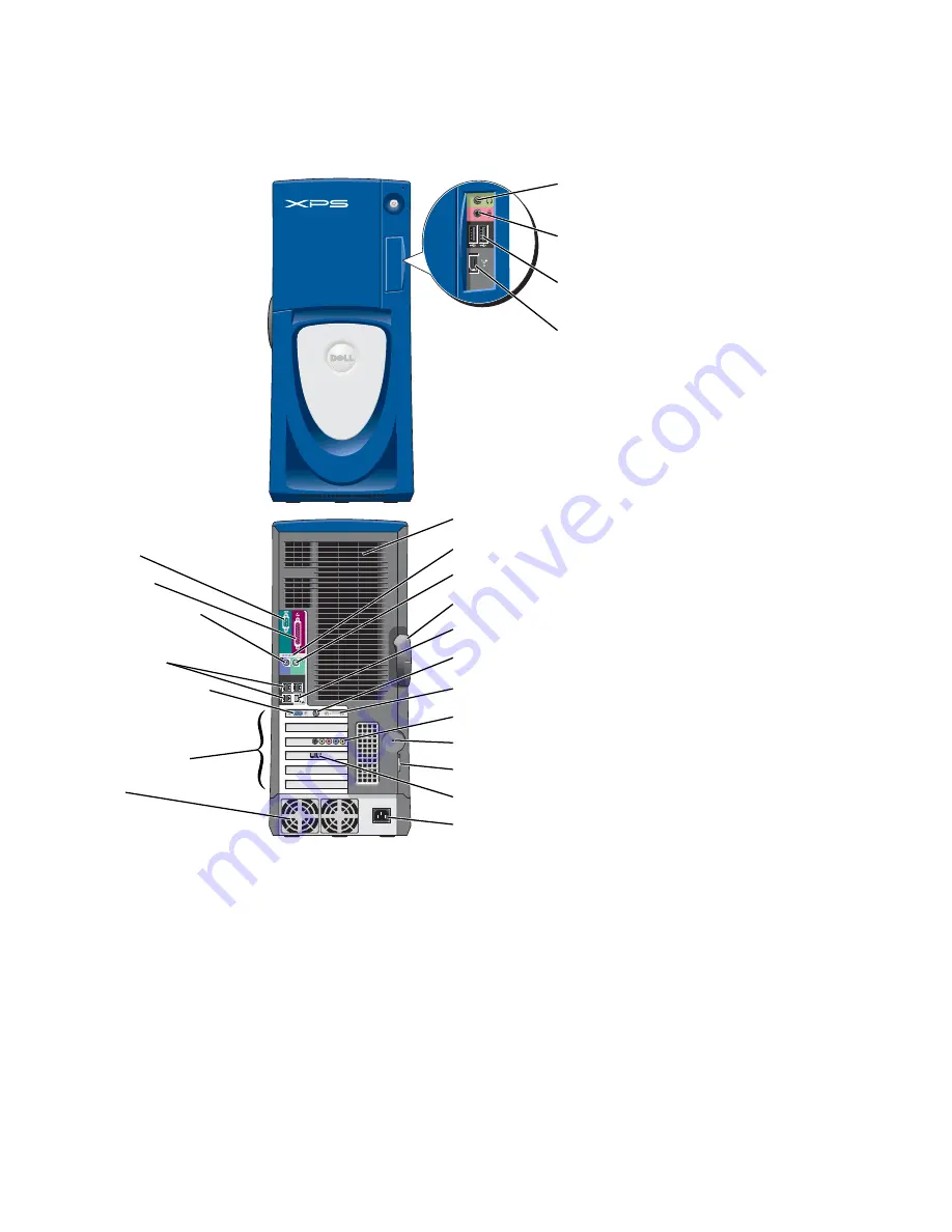
headphone
connector

microphone
connector

USB 2.0 
connectors (2)

IEEE 1394
connector

PCI card (4), PCI Express 
x1 card (1), PCI Express 
x16 card (1) slots

serial port

parallel port

diagnostic lights

keyboard connector

USB 2.0 
connectors (6)

VGA video connector

cover latch release

fans (2)

network adapter connector

security cable slot

fans (2)

sound card connectors

padlock ring

modem connector

power connector

DVI video connector

mouse connector

TV-OUT connector

Model WHL

Summary of Contents for DIMENSION XPS GEN 3 WHL

Page 1: ...4 PCI Express x1 card 1 PCI Express x16 card 1 slots serial port parallel port diagnostic lights keyboard connector USB 2 0 connectors 6 VGA video connector cover latch release fans 2 network adapter connector security cable slot fans 2 sound card connectors padlock ring modem connector power connector DVI video connector mouse connector TV OUT connector Model WHL ...

Page 2: ...ot applicable ____________________ Information in this document is subject to change without notice 2004 Dell Inc All rights reserved Reproduction in any manner whatsoever without the written permission of Dell Inc is strictly forbidden Trademarksusedinthistext Dell the DELLlogo Inspiron DellPrecision Dimension OptiPlex Latitude PowerEdge PowerVault PowerApp DellNet PowerConnect and Axim are trade...

Page 3: ...y Settings 17 About Serial ATA Drives 17 About Your RAID Configuration 17 RAID Level 0 18 RAID Level 1 18 Configuring Your Computer for RAID 19 Configuring for RAID Using the Intel R Option ROM Utility 20 Configuring for RAID Using the Intel R Application Accelerator 21 Transferring Information to a New Computer 25 Copying CDs and DVDs 26 How to Copy a CD or DVD 26 Using Blank CD Rs CD RWs DVD Rs ...

Page 4: ... 36 The computer stops responding 36 A program stops responding 36 A program crashes repeatedly 37 A program is designed for an earlier Windows operating system 37 A solid blue screen appears 37 Other software problems 37 Memory Problems 38 Mouse Problems 38 Network Problems 39 Power Problems 40 Printer Problems 41 Scanner Problems 41 Sound and Speaker Problems 42 No sound from speakers 42 No soun...

Page 5: ...he Last System Restore 56 Resolving Software and Hardware Incompatibilities 57 Reinstalling Microsoft Windows XP 57 Before You Begin 57 Reinstalling Windows XP 58 5 Removing and Installing Parts Before You Begin 61 Recommended Tools 61 Turning Off Your Computer 61 Before Working Inside Your Computer 62 Front and Back View of the Computer 63 Front View 63 Front View Doors Open 64 Back View 65 Openi...

Page 6: ...oppy Drive 90 CD DVD Drive 92 Removing a CD DVD Drive 92 Installing a CD DVD Drive 93 Processor Airflow Shroud 96 Removing the Processor Airflow Shroud 96 Installing the Processor Airflow Shroud 97 Processor 97 Removing the Processor 97 Installing the Processor 100 Front Panel 102 Removing the Front Panel 102 Replacing the Front Panel 103 Drive Door 104 Removing the Drive Door 104 Replacing the Dr...

Page 7: ... 114 System Setup Options 115 Boot Sequence 118 Clearing Forgotten Passwords 119 Clearing CMOS Settings 120 Dell Technical Support Policy U S Only 121 Definition of Dell Installed Software and Peripherals 121 Definition of Third Party Software and Peripherals 121 Contacting Dell 121 Index 139 ...

Page 8: ...8 Contents ...

Page 9: ...documentation My device documentation ResourceCD Documentation and drivers are already installed on your computer You can use the CD to reinstall drivers see page 54 run the Dell Diagnostics see page 50 or access your documentation Readme files may be included on your CD to provide last minute updates about technical changes to your computer or advanced technical reference material for technicians...

Page 10: ...n Guide How to set up my computer Setup Diagram Tips on using Microsoft Windows How to play CDs and DVDs How to use standby mode and hibernate mode How to change my display resolution How to clean my computer The Dell Dimension Help file 1 Click the Start button and click Help and Support 2 Click User and system guides and click User s guides 3 Click Dell Dimension Help What Are You Looking For Fi...

Page 11: ...t site The Dell Support website provides several online tools including Solutions Troubleshooting hints and tips articles from technicians and online courses Community Online discussion with other Dell customers Upgrades Upgrade information for components such as memory the hard drive and the operating system Customer Care Contact information order status warranty and repair information Downloads ...

Page 12: ...d on your computer To reinstall your operating system use the Operating System CD See Reinstalling Microsoft Windows XP on page 57 After you reinstall your operating system use the ResourceCD to reinstall drivers for the devices that came with your computer NOTE The color of your CD varies based on the operating system you ordered What Are You Looking For Find it Here ...

Page 13: ...ng the Drive Door Changing the Backlight Color You can use this exclusive Dell Dimension XPS Gen 3 feature either to change the color of the backlight that illuminates the Dell name and displays around the badge on the front of your computer or to turn off the backlight entirely ...

Page 14: ... any of the procedures in this section follow the safety instructions located in the Product Information Guide NOTE The backlight is not for diagnostic purposes 1 Follow the procedures in Before You Begin on page 61 2 Turn on or restart your computer 3 Enter system setup see page 114 4 Scroll through the color options using the up and down arrow keys select System and then press Enter badge backli...

Page 15: ...tion to the TV NOTE See the documentation that came with your TV to ensure that you properly configure and connect the TV If you purchased a graphics card that supports dual monitors follow these instructions to connect and enable your monitors The instructions tell you how to connect either two monitors each with a VGA connector one monitor with a VGA connector and one monitor with a DVI connecto...

Page 16: ...on the back of the computer Connecting a TV NOTE To connect a TV to your computer you must purchase an S video cable which is available at most consumer electronics stores An S video cable is not included with your computer 1 Follow the procedures in Before You Begin on page 61 2 Connect one end of the S video cable to the TV OUT connector on the back of the computer 3 Connect the other end of the...

Page 17: ...outing this allows a more efficient utilization of space inside the chassis See Hard Drive on page 84 for information on serial ATA drive connections About Your RAID Configuration This section provides an overview of the RAID configuration that you might have selected when you purchased your computer Although several RAID configurations are available Dell offers either RAID level 0 or RAID level 1...

Page 18: ...apacities of the drives For example if you have two 120 GB drives installed you have 240 GB on which to store data NOTICE Because RAID level 0 provides no data redundancy if one drive fails then the data on the other drive is also inaccessible Therefore ensure that you perform regular backups when you use a RAID level 0 configuration RAID Level 1 RAID level 1 uses a data redundancy storage techniq...

Page 19: ...n ROM utility and is performed before you install the operating system onto the hard drive The second method uses the Intel Application Accelerator or Intel Storage Utility and this method is performed after you have installed the operating system and the Intel Storage Utility Both methods require that you set your computer to RAID enabled mode before starting any of the RAID configuration procedu...

Page 20: ...l R RAID Option ROM utility 3 Use the up and down arrow keys to highlight Create RAID Volume and press Enter 4 Enter a RAID volume name or accept the default and press Enter 5 Use the up and down arrow keys to select RAID0 Stripe and press Enter 6 If there are more than two hard disks available use the up and down arrow keys and space bar to select the two disks you want to use to make up your arr...

Page 21: ...ROM your computer will become unbootable 1 Press Ctrl i when you are prompted to enter the Intel RAID Option ROM utility 2 Use the up and down arrow keys to highlight Delete RAID Volume and press Enter 3 Use the up and down arrow keys to highlight the RAID volume you want to delete and press Delete 4 Press y to confirm the deletion of the RAID volume 5 Press Esc to exit the Intel Option ROM utilit...

Page 22: ...ate the volume or click Back to make changes Creating a RAID 1 Volume NOTE When you perform this operation all data on the RAID drives will be lost 1 Set your computer to RAID enabled mode see page 19 2 Click the Start button and point to Programs Intel R Application Accelerator Intel Application Accelerator to launch the Intel R Storage Utility NOTE If you do not see an Actions menu option you ha...

Page 23: ...tility NOTE If you do not see an Actions menu option you have not yet set your computer to RAID enabled mode see page 19 3 On the Actions menu select Create RAID Volume From Existing Hard Drive to launch the Migration Wizard 4 Click Next on the Migration Wizard screen 5 Enter a RAID volume name or accept the default 6 From the drop down box select RAID 0 as the RAID level NOTE Select the strip siz...

Page 24: ...ource Hard Drive screen double click the hard drive from which you want to migrate and click Next 8 On the Select Member Hard Drive screen double click the hard drive to select the member drive that you want to act as the mirror in the array and click Next 9 On the Specify Volume Size screen select the volume size you want and click Next NOTE In the following step you will lose all data contained ...

Page 25: ...and Settings Transfer wizard to move data from the source computer to the new computer You can move data such as E mails Toolbar settings Window sizes Internet bookmarks You can transfer the data to the new computer over a network or serial connection or you can store it on a removable medium such as a writable CD or floppy disk To prepare the new computer for the file transfer 1 Click the Start b...

Page 26: ...NOTE Ensure that you follow all copyright laws when you create CDs or DVDs This section applies only to computers that have a CD R CD RW DVD RW DVD R or DVD CD RW combo drive NOTE The types of CD or DVD drives offered by Dell may vary by country The following instructions show how to make an exact copy of a CD or DVD You can also use Sonic RecordNow for other purposes including creating CDs from a...

Page 27: ... of recording media CD Rs and CD RWs including High Speed CD RWs Use blank CD Rs to record music or permanently store data files After creating a CD R you cannot write to that CD R again see the Sonic documentation for more information Use blank CD RWs to write to CDs or to erase rewrite or update data on CDs Your DVD writable drive can write to four different types of recording media CD Rs CD RWs...

Page 28: ...See the Sonic support website at support sonic com for additional information Network Setup Wizard The Microsoft Windows XP operating system provides a Network Setup Wizard to guide you through the process of sharing files printers or an Internet connection between computers in a home or small office 1 Click the Start button point to All Programs Accessories Communications and then click Network S...

Page 29: ... can enable or disable Hyper Threading through system setup For more information on accessing system setup see page 113 For more information on Hyper Threading search the Knowledge Base on the Dell Support website at support dell com Overclocking Dell locks the processor multiplier options in system setup to prevent processor overclocking The first and most important reason for preventing overcloc...

Page 30: ... card slot The PCI Express x16 card slot replaces the AGP graphics card slot Some benefits of PCI Express technology include Greater available bandwidth PCI Express bus bandwidth is 250 MB s in each direction simultaneously while PCI bus bandwidth is 133 MB s in one direction at a time Prioritization of service Multiple PCI cards installed in a computer all share a common bus but each PCI Express ...

Page 31: ...ed by the manufacturer Discard used batteries according to the manufacturer s instructions CAUTION Before you begin any of the procedures in this section follow the safety instructions located in the Product Information Guide Drive Problems CAUTION Before you begin any of the procedures in this section follow the safety instructions located in the Product Information Guide REPLACE THE BATTERY If y...

Page 32: ...TIONS RUN THE HARDWARE TROUBLESHOOTER See page 57 RUN THE DELL DIAGNOSTICS See page 50 ADJUST THE WINDOWS VOLUME CONTROL Click the speaker icon in the lower right corner of your screen Ensure that the volume is turned up by clicking the slidebar and dragging it up Ensure that the sound is not muted by clicking any boxes that are checked CHECK THE SPEAKERS AND SUBWOOFER See Sound and Speaker Proble...

Page 33: ...k CHECK THE TELEPHONE LINE CONNECTION CHECK THE TELEPHONE JACK CONNECT THE MODEM DIRECTLY TO THE TELEPHONE WALL JACK USE A DIFFERENT TELEPHONE LINE Verify that the telephone line is connected to the jack on the modem The jack has either a green label or a connector shaped icon next to it Ensure that you hear a click when you insert the telephone line connector into the modem Disconnect the telepho...

Page 34: ...rly ENSURE THAT YOU ARE CONNECTED TO THE INTERNET Ensure that you have subscribed to an Internet provider With the Outlook Express e mail program open click File If Work Offline has a checkmark next to it click the checkmark to remove it and connect to the Internet For help contact your Internet service provider A FILENAME CANNOT CONTAIN ANY OF THE FOLLOWING CHARACTERS Do not use these characters ...

Page 35: ...SURE THAT THE CABLE FOR THE IEEE 1394 DEVICE IS PROPERLY INSERTED INTO THE DEVICE AND INTO THE CONNECTOR ON THE COMPUTER ENSURE THAT THE IEEE 1394 DEVICE IS RECOGNIZED BY WINDOWS 1 Click the Start button and click Control Panel 2 Click Printers and Other Hardware If your IEEE 1394 device is listed Windows recognizes the device IF YOU HAVE PROBLEMS WITH A DELL IEEE 1394 DEVICE Contact Dell see page...

Page 36: ...onnect a properly working keyboard to the computer and try using the keyboard RUN THE HARDWARE TROUBLESHOOTER See page 57 CHECK THE DIAGNOSTIC LIGHTS See page 47 ENSURE THAT THE POWER CABLE IS FIRMLY CONNECTED TO THE COMPUTER AND TO THE ELECTRICAL OUTLET TURN THE COMPUTER OFF If you are unable to get a response by pressing a key on your keyboard or moving your mouse press and hold the power button...

Page 37: ...e welcome screen click Next 3 Follow the instructions on the screen TURN THE COMPUTER OFF If you are unable to get a response by pressing a key on your keyboard or moving your mouse press and hold the power button for at least 8 to 10 seconds until the computer turns off Then restart your computer CHECK THE SOFTWARE DOCUMENTATION OR CONTACT THE SOFTWARE MANUFACTURER FOR TROUBLESHOOTING INFORMATION...

Page 38: ... If necessary install additional memory see page 109 Reseat the memory modules see page 70 to ensure that your computer is successfully communicating with the memory Run the Dell Diagnostics see page 50 IF YOU EXPERIENCE OTHER MEMORY PROBLEMS Reseat the memory modules see page 70 to ensure that your computer is successfully communicating with the memory Ensure that you are following the memory ins...

Page 39: ...and then click Printers and Other Hardware 2 Click Mouse 3 Try adjusting the settings REINSTALL THE MOUSE DRIVER See page 54 RUN THE HARDWARE TROUBLESHOOTER See page 57 CHECK THE NETWORK CABLE CONNECTOR Ensure that the network cable is firmly inserted into both the network connector on the back of the computer and the network jack CHECK THE NETWORK LIGHTS ON THE BACK OF THE COMPUTER If the link in...

Page 40: ...r strips and power extension cables to verify that the computer turns on properly Ensure that the electrical outlet is working by testing it with another device such as a lamp Ensure that the main power cable and front panel cable are securely connected to the system board see page 69 IF THE POWER LIGHT IS BLINKING The computer is receiving electrical power but an internal power problem might exis...

Page 41: ...er documentation for cable connection information Ensure that the printer cables are securely connected to the printer and the computer TEST THE ELECTRICAL OUTLET Ensure that the electrical outlet is working by testing it with another device such as a lamp VERIFY THAT THE PRINTER IS RECOGNIZED BY WINDOWS 1 Click the Start button click Control Panel and then click Printers and Other Hardware 2 Clic...

Page 42: ...nner and the computer VERIFY THAT THE SCANNER IS RECOGNIZED BY MICROSOFT WINDOWS 1 Click the Start button click Control Panel and then click Printers and Other Hardware 2 Click Scanners and Cameras If your scanner is listed Windows recognizes the scanner REINSTALL THE SCANNER DRIVER See the scanner documentation for instructions CHECK THE SPEAKER CABLE CONNECTIONS Ensure that the speakers are conn...

Page 43: ...lamp ELIMINATE POSSIBLE INTERFERENCE Turn off nearby fans fluorescent lights or halogen lamps to check for interference RUN THE SPEAKER DIAGNOSTICS REINSTALL THE SOUND DRIVER See page 53 RUN THE HARDWARE TROUBLESHOOTER See page 57 CHECK THE HEADPHONE CABLE CONNECTION Ensure that the headphone cable is securely inserted into the headphone connector see page 64 ADJUST THE WINDOWS VOLUME CONTROL Clic...

Page 44: ...T If the power light is off firmly press the button to ensure that the monitor is turned on If the power light is lit or blinking the monitor has power If the power light is blinking press a key on the keyboard or move the mouse TEST THE ELECTRICAL OUTLET Ensure that the electrical outlet is working by testing it with another device such as a lamp CHECK THE DIAGNOSTIC LIGHTS See page 47 CHECK THE ...

Page 45: ...JUST THE WINDOWS DISPLAY SETTINGS 1 Click the Start button click Control Panel and then click Appearance and Themes 2 Click Display and click the Settings tab 3 Try different settings for Screen resolution and Color quality ...

Page 46: ...46 Solving Problems w w w d e l l c o m s u p p o r t d e l l c o m ...

Page 47: ... When the computer starts normally the lights flash After the computer starts all four lights display solid green If the computer malfunctions the color and sequence of the lights identify the problem Light Pattern Problem Description Suggested Resolution The computer is in a normal off condition or a possible pre BIOS failure has occurred Plug the computer into a working electrical outlet and pre...

Page 48: ...f the problem persists contact Dell see page 121 A possible graphics card failure has occurred If the computer has a graphics card remove the card see page 81 reinstall it and then restart the computer If the problem still exists install a graphics card that you know works and restart the computer If the problem persists or the computer has integrated graphics contact Dell see page 121 A possible ...

Page 49: ...mory module memory connector placement requirements exist see page 70 Verify that the memory modules that you are installing are compatible with your computer see page 70 If the problem persists contact Dell see page 121 A possible expansion card failure has occurred 1 Determine if a conflict exists by removing a card not a graphics card and restarting the computer see page 74 2 If the problem per...

Page 50: ...the Dell Dimension ResourceCD Another failure has occurred Ensure that the cables are properly connected to the system board from the hard drive CD drive and DVD drive see page 69 If there is an error message on your screen identifying a problem with a device such as the floppy drive or hard drive check the device to make sure it is functioning properly The operating system is attempting to boot f...

Page 51: ...ourceCD 2 Shut down and restart the computer see page 61 When the DELL logo appears press F12 immediately If you wait too long and the Windows logo appears continue to wait until you see the Windows desktop Then shut down your computer see page 61 and try again NOTE The next steps change the boot sequence for one time only On the next start up the computer boots according to the devices specified ...

Page 52: ... applicable tab described in the following table for more information Option Function Express Test Performs a quick test of devices This test typically takes 10 to 20 minutes and requires no interaction on your part Run Express Test first to increase the possibility of tracing the problem quickly Extended Test Performs a thorough check of devices This test typically takes an hour or more and requi...

Page 53: ...tems that are not on your computer Ensure that you are installing software appropriate for your operating system Many drivers such as the keyboard driver come with your Microsoft Windows operating system You may need to install drivers if you Upgrade your operating system Reinstall your operating system Connect or install a new device Identifying Drivers If you experience a problem with any device...

Page 54: ... your computer after you install or update a driver use Windows XP Device Driver Rollback to replace the driver with the previously installed version 1 Click the Start button and click Control Panel 2 Under Pick a Category click Performance and Maintenance 3 Click System 4 In the System Properties window click the Hardware tab 5 Click Device Manager 6 Right click the device for which the new drive...

Page 55: ...nstalling Drivers 1 After extracting the driver files to your hard drive as described in the previous section click the Start button and right click My Computer 2 Click Properties 3 Click the Hardware tab and click Device Manager 4 Double click the type of device for which you are installing the driver 5 Double click the name of the device for which you are installing the driver 6 Click the Driver...

Page 56: ...re your computer The Select a Restore Point screen provides a calendar that allows you to see and select restore points All calendar dates with available restore points appear in boldface type 4 Select a restore point and click Next If a calendar date has only one restore point then that restore point is automatically selected If two or more restore points are available click the restore point tha...

Page 57: ...t button and click Help and Support 2 Type hardware troubleshooter in the Search field and click the arrow to start the search 3 Click Hardware Troubleshooter in the Search Results list 4 In the Hardware Troubleshooter list click I need to resolve a hardware conflict on my computer and click Next Reinstalling Microsoft Windows XP NOTICE You must use Windows XP Service Pack 1 SP1 or later when you ...

Page 58: ...indows XP disable any virus protection software installed on your computer before you reinstall Windows XP See the documentation that came with the software for instructions Booting From the Operating System CD 1 Save and close any open files and exit any open programs 2 Insert the Operating System CD Click Exit if Install Windows XP message appears 3 Restart the computer 4 Press F12 immediately a...

Page 59: ... a name for your computer or accept the one provided and a password and click Next 9 If the Modem Dialing Information screen appears enter the requested information and click Next 10 Enter the date time and time zone in the Date and Time Settings window and click Next 11 If the Networking Settings screen appears click Typical and click Next 12 If you are reinstalling Windows XP Professional and yo...

Page 60: ...rivers with the ResourceCD see page 54 20 Reinstall your virus protection software 21 Reinstall your programs NOTE To reinstall and activate your Microsoft Office or Microsoft Works Suite programs you need the Product Key number located on the back of the Microsoft Office or Microsoft Works Suite CD sleeve ...

Page 61: ...is document may require the following tools Small flat blade screwdriver Phillips screwdriver Flash BIOS update program floppy disk or CD Turning Off Your Computer NOTICE To avoid losing data save and close any open files and exit any open programs before you turn off your computer 1 Shut down the operating system a Save and close any open files exit any open programs click the Start button and th...

Page 62: ...ress in on the locking tabs before you disconnect the cable As you pull connectors apart keep them evenly aligned to avoid bending any connector pins Also before you connect a cable ensure that both connectors are correctly oriented and aligned NOTICE To avoid damaging the computer perform the following steps before you begin working inside the computer 1 Turn off your computer see page 61 NOTICE ...

Page 63: ...ing 2 power button Press to turn on the computer NOTICE To avoid losing data do not use the power button to turn off the computer Instead perform an operating system shutdown 3 drive door Open the drive door to access the floppy and CD DVD drives 4 front panel door Open the door to use the front panel connectors NOTE The front door is removable if you remove it or accidentally knock it off its hin...

Page 64: ...ector to attach a personal computer microphone for voice or musical input into a sound or telephony program 3 USB 2 0 connectors 2 Use the front USB connectors for devices that you connect occasionally such as joysticks or cameras It is recommended that you use the back USB connectors for devices that typically remain connected such as printers and keyboards 4 IEEE 1394 connector Attach high speed...

Page 65: ...k or broadband device connect one end of a network cable to either a network jack or to your network or broadband device Connect the other end of the network cable to the network adapter connector on the back panel of your computer A click indicates that the network cable has been securely attached NOTE Do not plug a telephone cable into the network connector On computers with a network connector ...

Page 66: ...10 optional modem connector If you have a modem connect a telephone cable to the modem connector optional NOTE For optimum performance install a modem card only in PCI slot 2 3 or 4 NOTE Do not plug a telephone cable into the network connector 11 power connector Insert the power cable 12 serial connector COM 1 Connect a serial device such as a handheld device to the serial port 13 parallel connect...

Page 67: ...uter s electronic components You can do so by touching an unpainted metal surface on the computer chassis 1 Follow the procedures in Before You Begin see page 61 2 Lay the computer on its side so that the arrow on the bottom of the computer points up NOTICE Ensure that sufficient space exists to accommodate the open cover at least 30 cm 1 ft of desk top space 3 Slide the cover release latch toward...

Page 68: ...ts w w w d e l l c o m s u p p o r t d e l l c o m Inside View of Your Computer hard drive shroud floppy drive CD DVD drive system board processor airflow shroud power supply processor fan power supply fans 2 PCI card shroud and fan ...

Page 69: ...connector PWR internal speaker SPKR serial ATA connectors SATA 0 SATA 1 SATA 2 SATA 3 password jumper PASS PCI card connectors PCI SLOT 1 PCI SLOT 2 PCI SLOT 3 PCI SLOT 4 PCI Express x16 card connector memory module connectors 2 4 clear CMOS jumper CMOS PCI Express x1 card connector floppy drive connector FLOPPY memory module connectors 1 3 processor fan CPU FAN power connector 12V PWR card fan co...

Page 70: ...rformance See the label on the upper right corner of the module to determine the module s capacity NOTE Always install DDR2 memory modules in the order indicated on the system board The recommended memory configurations are A pair of matched memory modules installed in DIMM connectors 1 and 2 or A pair of matched memory modules installed in DIMM connectors 1 and 2 and another matched pair installe...

Page 71: ...ss space however the amount of memory available to the operating system is less than 4 GB Certain components within the computer require address space in the 4 GB range Any address space reserved for these components cannot be used by computer memory Installing Memory CAUTION Before you begin any of the procedures in this section follow the safety instructions located in the Product Information Gu...

Page 72: ...tor NOTICE To avoid damage to the memory module press the module straight down into the connector while you apply equal force to each end of the module 5 Insert the module into the connector until the module snaps into position If you insert the module correctly the securing clips snap into the cutouts at each end of the module securing clips 2 connector memory connector closest to processor notch...

Page 73: ... discharge static electricity from your body before you touch any of your computer s electronic components You can do so by touching an unpainted metal surface on the computer chassis 1 Follow the procedures in Before You Begin on page 61 2 Press out the securing clip at each end of the memory module connector 3 Grasp the module and pull up If the module is difficult to remove gently ease the modu...

Page 74: ...in the next section If you are removing but not replacing a card see Removing a PCI Card on page 76 If you are replacing a card remove the current driver for the card from the operating system If you are installing or replacing a PCI Express card see Installing a PCI Express Card on page 78 Installing a PCI Card 1 Follow the procedures in Before You Begin on page 61 2 Press the lever on the card r...

Page 75: ...re connected to a network To guard against electrical shock be sure to unplug your computer from its electrical outlet before installing any cards 6 Place the card in the connector and press down firmly Ensure that the card is fully seated in the slot If the card is full length insert the end of the card into the card guide bracket as you lower the card toward its connector on the system board Ins...

Page 76: ...en turn them on 11 If you installed an add in network adapter and you want to disable the integrated network adapter a Enter system setup see page 113 select Integrated Devices and then change the setting for Network Interface Card to Off b Connect the network cable to the add in network adapter s connectors Do not connect the network cable to the integrated connector on the back panel 12 Install ...

Page 77: ...d s driver from the operating system 9 If you removed an add in network connector and want to enable the integrated network adapter a Enter system setup select Integrated Devices and then change the setting for Network Interface Card to On b Connect the network cable to the integrated connector on the back panel of the computer PCI Express Cards Your computer supports one PCI Express x16 card and ...

Page 78: ...ss Card 1 Follow the procedures in Before You Begin on page 61 2 Press the lever on the card retention arm and raise the retention arm edge connector card connector filler bracket retention arm lever securing tab securing slot edge connector card connector top of retention mechanism tab x16 card x1 card ...

Page 79: ...ernal connections or otherwise customizing it for your computer CAUTION Some network adapters automatically start the computer when they are connected to a network To guard against electrical shock be sure to unplug your computer from its electrical outlet before installing any cards 6 If you are installing the card into the x16 card connector position the card so the securing slot is aligned with...

Page 80: ...ipment 11 Connect any cables that should be attached to the card See the documentation that came with the card for information about the card s cable connections NOTICE To connect a network cable first plug the cable into the network wall jack and then plug it into the computer 12 Close the computer cover reconnect the computer and devices to electrical outlets and then turn them on 13 If you inst...

Page 81: ...Installing filler brackets over empty card slot openings is necessary to maintain FCC certification of the computer The brackets also keep dust and dirt out of your computer 7 Lower the retention arm and press it into place securing the card s in the computer NOTICE To connect a network cable first plug the cable into the network wall jack and then plug it into the computer 8 Close the computer co...

Page 82: ...TA 3 Connect CD DVD drives to the connector labeled PRI IDE When you connect two IDE devices to a single IDE interface cable and configure them for the cable select setting the device attached to the last connector on the interface cable is the primary or the boot device drive 0 and the device attached to the middle connector on the interface cable is the secondary device drive 1 See the drive doc...

Page 83: ...ce connectors are keyed for correct insertion that is a notch or a missing pin on one connector matches a tab or a filled in hole on the other connector When you connect an IDE cable ensure that you align the colored stripe with the pin 1 connector When you disconnect an IDE cable grasp the colored pull tab and pull until the connector detaches When connecting and disconnecting a serial ATA cable ...

Page 84: ...e to the drive do not set it on a hard surface Instead set the drive on a surface such as a foam pad that will sufficiently cushion it 1 If you are replacing a hard drive that contains data you want to keep back up your files before you remove the hard drive 2 Follow the procedures in Before You Begin on page 61 Removing a Hard Drive 1 Press in on the top shroud tabs and tilt the shroud back 2 Lif...

Page 85: ...tation for the drive to verify that it is configured for your computer 3 If your replacement hard drive does not have the bracket rails attached remove the rails from the old drive by removing the two screws that secure each rail to the drive Attach the bracket rails to the new drive by aligning the screw holes on the drive with the screw holes on the bracket rails and then inserting and tightenin...

Page 86: ...rd drive in the lower bay place the drive in the bay so that the power connector is on the left hand side opposite of the top hard drive 5 Connect a power cable to the drive 6 Connect the hard drive cable to the drive and to the system board see page 69 7 Check all connectors to be certain that they are properly cabled and firmly seated drive screws 4 bracket rails 2 hard drive hard drive cable po...

Page 87: ...e computer cover see page 108 NOTICE To connect a network cable first plug the cable into the network wall jack and then plug it into the computer 12 Connect your computer and devices to electrical outlets and turn them on See the documentation that came with the drive for instructions on installing any software required for drive operation 13 If the drive you just installed is the primary drive i...

Page 88: ...fficiently cushion it 1 Check the documentation for the drive to verify that it is configured for your computer 2 Follow the procedures in Before You Begin on page 61 3 Remove the two plastic rails from the inside of the hard drive bay by gently pulling the rails up and out of the bay 4 Attach the rails to the hard drive using the two screws attached to the rails Ensure that the rail tabs are posi...

Page 89: ...equired for drive operation Floppy Drive CAUTION Before you begin any of the procedures in this section follow the safety instructions located in the Product Information Guide CAUTION To guard against electrical shock always unplug your computer from the electrical outlet before opening the cover Follow the procedure in Before You Begin on page 61 NOTE If you are adding a floppy drive see Installi...

Page 90: ...ve 1 If you are replacing a drive and the new drive does not have the bracket rails attached remove the rails from the old drive by removing the two screws that secure each rail to the drive Attach the bracket to the new drive by aligning the screw holes on the drive with the screw holes on the bracket rails and then inserting and tightening all four screws two screws on each rail data cable power...

Page 91: ...Removing and Installing Parts 91 2 Gently slide the drive into place until the tabs securely click into position drive screws 4 bracket rails 2 data cable power cable tabs 2 floppy drive ...

Page 92: ... to electrical outlets and turn them on See the documentation that came with the drive for instructions on installing any software required for drive operation 8 Enter system setup see page 113 and update the appropriate Diskette Drive option 9 Verify that your computer works correctly by running the Dell Diagnostics see page 50 CD DVD Drive CAUTION Before you begin any of the procedures in this s...

Page 93: ...nd prepare it for installation Check the documentation that accompanied the drive to verify that the drive is configured for your computer If you are installing an IDE drive configure the drive for the cable select setting 2 Connect the new drive to the set of rails that are attached to the inside of the cover If a set of rails is not attached inside the computer cover call Dell see page 121 power...

Page 94: ... drive Attach the bracket to the new drive by aligning the screw holes on the drive with the screw holes on the bracket rails and then inserting and tightening all four screws two screws on each rail 4 Gently slide the drive into place until the tabs securely click into position 5 Connect the power and data cables to the drive If you are adding a drive that has an audio cable connect the audio cab...

Page 95: ...twork wall jack and then plug it into the computer 8 Connect your computer and devices to electrical outlets and turn them on See the documentation that came with the drive for instructions on installing any software required for drive operation 9 Enter system setup see page 69 and select the appropriate Drive option 10 Verify that your computer works correctly by running the Dell Diagnostics see ...

Page 96: ...from your body before you touch any of your computer s electronic components You can do so by touching an unpainted metal surface on the computer chassis NOTICE To avoid damaging the fan power cables do not slide the shroud too quickly 1 Follow the procedures in Before You Begin on page 61 2 Press the shroud release lever towards the front of the computer 3 Lift the shroud up to disengage the anch...

Page 97: ... the Processor NOTICE Do not perform the following steps unless you are familiar with hardware removal and replacement Performing these steps incorrectly could damage your system board For technical service see Contacting Dell on page 121 CAUTION Before you begin any of the procedures in this section follow the safety instructions located in the Product Information Guide 1 Follow the procedures in...

Page 98: ...ON The heat sink can get very hot during normal operation Be sure that the heat sink has had sufficient time to cool before you touch it 5 Remove the heat sink a Remove the retention module clips Press the tabs toward the center of the clip and lift up anchor tabs 3 shroud release lever ...

Page 99: ...eat sink up and out of the retention base NOTICE Lay the heat sink down on its side NOTICE If you are installing a processor upgrade kit from Dell discard the original heat sink If you are not installing a processor upgrade kit from Dell reuse the original heat sink and blower when you install your new processor 6 Push down and out on the socket release lever 7 Open the processor cover heat sink r...

Page 100: ...NOTICE Ground yourself by touching an unpainted metal surface on the back of the computer 1 Unpack the new processor NOTICE You must position the processor correctly in the socket to avoid permanent damage to the processor and the computer when you turn on the computer 2 If the release lever on the socket is not fully extended move it to that position 3 Align the pin 1 corners of the processor and...

Page 101: ...with minimal pressure to seat it 5 When the processor is fully seated in the socket close the processor cover 6 Pivot the socket release lever back toward the socket and snap it into place to secure the processor NOTICE If you are not installing a processor upgrade kit from Dell reuse the original heat sink assembly when you replace the processor If you installed a processor replacement kit from D...

Page 102: ...he computer cover NOTICE To connect a network cable first plug the cable into the network wall jack and then plug it into the computer 13 Connect your computer and devices to electrical outlets and turn them on Front Panel CAUTION To prevent static damage to components inside your computer discharge static electricity from your body before you touch any of your computer s electronic components You...

Page 103: ...ving and Installing Parts 103 4 Close the computer cover halfway and pull the front panel away from the computer Replacing the Front Panel To replace the front panel perform the removal procedure in reverse ...

Page 104: ...w w d e l l c o m s u p p o r t d e l l c o m Drive Door CAUTION Before you begin any of the procedures in this section follow the safety instructions located in the Product Information Guide Removing the Drive Door 1 Open the drive door ...

Page 105: ...e computer if it is opened too far If the drive door detaches from the computer without disassembling perform the removal procedure in reverse If the drive door is open and it is opened too far instead of breaking away from the computer in one piece the drive door may disassemble into several smaller pieces If the drive door disassembles 1 If necessary reattach the door hinges to the door bracket ...

Page 106: ...Attach the door bracket door hinge assembly to the door starting with the lower part of each door hinge 3 Attach the drive door to the computer starting with the bottom bracket hinge door bracket hinge tab door hinges 2 lower part of the door hinge door door bracket door hinge assembly ...

Page 107: ...type recommended by the manufacturer Discard used batteries according to the manufacturer s instructions To replace the battery 1 Record all the screens in system setup see page 113 so that you can restore the correct settings in step 8 2 Follow the procedures in Before You Begin on page 61 3 Locate the battery socket see page 69 NOTICE If you pry the battery out of its socket with a blunt object ...

Page 108: ... Closing the Computer Cover 1 Ensure that all cables are connected and fold cables out of the way 2 Ensure that no tools or extra parts are left inside the computer 3 Pivot the cover down and into position 4 Press down on the cover to close it 5 Once the cover is closed slide the release latch to the right until the latch clicks into place 6 If you are using a padlock to secure your computer insta...

Page 109: ...3 MHz DDR2 unbuffered SDRAM Memory connectors 4 Memory capacities 128 256 512 or 1 GB non ECC Minimum memory 256 MB Maximum memory 4 GB NOTE See Addressing Memory With 4 GB Configurations on page 71 to verify the amount of memory available to the operating system BIOS address F0000h Computer Information Chipset Intel 925X Express DMA channels eight Interrupt levels 24 BIOS chip NVRAM 4 Mb NIC Inte...

Page 110: ...or size 120 pins connector data width maximum 32 bits PCI Express connector one x1 connector size 36 pins connector data width maximum 1 PCI Express lane PCI Express connector one x16 connector size 164 pins connector data width maximum 16 PCI Express lanes Drives Externally accessible two 3 5 inch drive bays two 5 25 inch drive bays Available devices Serial ATA drive floppy drive memory devices C...

Page 111: ...cts LFE channel two front panel connectors for headphones and microphones System board connectors Primary IDE drive 40 pin connector on PCI local bus Serial ATA four 7 pin connectors Floppy drive 34 pin connector Fan 5 pin connector PCI 2 3 four 120 pin connectors PCI Express x1 36 pin connector PCI Express x16 164 pin connector Telephony TAPI 4 pin connector Controls and Lights Power control push...

Page 112: ... Lights on page 47 Standby power light AUX_PWR on the system board Case backlight color options off no light ruby emerald sapphire default amber amethyst topaz diamond See Changing the Backlight Color on page 13 Power DC power supply Wattage 460 W Heat dissipation 931 2 BTU hr Voltage see the safety instructions located in the Product Information Guide for important voltage setting information fix...

Page 113: ... do not change the settings for this program Certain changes can make your computer work incorrectly Environmental Temperature Operating 10 to 35 C 50 to 95 F NOTE At 35 C 95 F the maximum operating altitude is 914 m 3000 ft Storage 40 to 65 C 40 to 149 F Relative humidity 20 to 80 noncondensing Maximum vibration Operating 0 25 G at 3 to 200 Hz at 0 5 octave min Storage 0 5 G at 3 to 200 Hz at 1 o...

Page 114: ...is field appears on the left side of the system setup window The field is a scrollable list containing features that define the configuration of your computer including installed hardware power conservation and security features Scroll up and down the list with the up and down arrow keys As an option is highlighted the Option Field displays more information about that option and the option s curre...

Page 115: ...s Diskette Drive Identifies and defines the floppy drive attached to the FLOPPY connector on the system board as Off USB Internal or Read Only Drives 0 through 5 Identifies the drives attached to the SATA or PRI IDE connectors on the system board and lists the capacity for hard drives Drive Controller Identifies and defines the SATA controller settings for RAID You can set the SATA controller to R...

Page 116: ... Quiet default The hard drive operates at its most quiet setting Suggested The hard drive operates at the level suggested by the drive manufacturer Performance The hard drive operates at its maximum speed NOTE Switching to performance mode may cause the drive to be noisier but its performance is not affected NOTE Changing the acoustics setting does not alter your hard drive image Security This sec...

Page 117: ...wered up remotely from suspend mode hibernate mode or when powered off When Low Power Mode in the Power Management menu is enabled the computer can only be powered up remotely from Suspend Suspend Mode The options are S1 a suspend state where the computer is running in a low power mode and S3 a standby state where the power is reduced or turned off for most components however system memory remains...

Page 118: ...evice documentation Changing Boot Sequence for the Current Boot You can use this feature for example to tell the computer to boot from the CD drive so that you can run the Dell Diagnostics on the Dell Dimension ResourceCD but you want the computer to boot from the hard drive when the diagnostic tests are complete You can also use this feature to restart your computer to a USB device such as a flop...

Page 119: ...arrow keys to highlight the Boot Sequence menu option and press Enter to access the menu NOTE Write down your current boot sequence in case you want to restore it 3 Press the up and down arrow keys to move through the list of devices 4 Press the spacebar to enable or disable a device enabled devices have a checkmark 5 Press plus or minus to move a selected device up or down the list Clearing Forgo...

Page 120: ...to pins 1 and 2 to reenable the password feature 10 Replace the computer cover see page 108 NOTICE To connect a network cable first plug the cable into the network wall jack and then plug it into the computer 11 Connect your computer and devices to electrical outlets and turn them on Clearing CMOS Settings CAUTION Before you begin any of the procedures in this section follow the safety instruction...

Page 121: ... Dell also extends a parts replacement program to cover all nonstandard third party hardware components integrated through CFI for the duration of the com puter s service contract Definition of Dell Installed Software and Peripherals Dell installed software includes the operating system and some of the software programs that are installed on the computer during the manufacturing process Microsoft ...

Page 122: ...ort Fax 11 4515 7139 Customer Care Fax 11 4515 7138 Aruba General Support toll free 800 1578 Australia Sydney International Access Code 0011 Country Code 61 City Code 2 E mail Australia au_tech_support dell com E mail New Zealand nz_tech_support dell com Home and Small Business 1 300 65 55 33 Government and Business toll free 1 800 633 559 Preferred Accounts Division PAD toll free 1 800 060 889 Cu...

Page 123: ...0671 Bolivia General Support toll free 800 10 0238 Brazil International Access Code 00 Country Code 55 City Code 51 Website www dell com br Customer Support Technical Support 0800 90 3355 Tech Support Fax 51 481 5470 Customer Care Fax 51 481 5480 Sales 0800 90 3390 British Virgin Islands General Support toll free 1 866 278 6820 Brunei Country Code 673 Customer Technical Support Penang Malaysia 604...

Page 124: ...e Sales Small Business toll free 1 800 847 4096 Technical Support med large bus government toll free 1 800 387 5757 Sales Home Sales Small Business toll free 1 800 387 52 Sales med large bus government toll free 1 800 387 5755 Spare Parts Sales Extended Service Sales 1 866 440 3355 Cayman Islands General Support 1 800 805 7541 Chile Santiago Country Code 56 City Code 2 Sales Customer Support and T...

Page 125: ... GCP toll free 800 858 2055 Large Corporate Accounts Key Accounts toll free 800 858 2628 Large Corporate Accounts North toll free 800 858 2999 Large Corporate Accounts North Government and Education toll free 800 858 2955 Large Corporate Accounts East toll free 800 858 2020 Large Corporate Accounts East Government and Education toll free 800 858 2669 Large Corporate Accounts Queue Team toll free 8...

Page 126: ...omputers den_support dell com E mail Support servers Nordic_server_support dell com Technical Support 7023 0182 Customer Care Relational 7023 0184 Home Small Business Customer Care 3287 5505 Switchboard Relational 3287 1200 Fax Switchboard Relational 3287 1201 Switchboard Home Small Business 3287 5000 Fax Switchboard Home Small Business 3287 5001 Dominica General Support toll free 1 866 278 6821 D...

Page 127: ...ntry Code 33 City Codes 1 4 Website support euro dell com E mail support euro dell com fr fr emaildell Home and Small Business Technical Support 0825 387 270 Customer Care 0825 823 833 Switchboard 0825 004 700 Switchboard calls from outside of France 04 99 75 40 00 Sales 0825 004 700 Fax 0825 004 701 Fax calls from outside of France 04 99 75 40 01 Corporate Technical Support 0825 004 719 Customer ...

Page 128: ...8844140083 Switchboard 2108129800 Sales 2108129800 Fax 2108129812 Grenada General Support toll free 1 866 540 3355 Guatemala General Support 1 800 999 0136 Guyana General Support toll free 1 877 270 4609 Hong Kong International Access Code 001 Country Code 852 Website support ap dell com E mail ap_support dell com Technical Support Dimension and Inspiron 2969 3189 Technical Support OptiPlex Latitu...

Page 129: ...d Sales 01 204 4444 U K Sales dial within U K only 0870 907 4000 Fax SalesFax 01 204 0103 Switchboard 01 204 4444 Italy Milan International Access Code 00 Country Code 39 City Code 02 Website support euro dell com E mail support euro dell com it it emaildell Home and Small Business Technical Support 02 577 826 90 Customer Care 02 696 821 14 Fax 02 696 821 13 Switchboard 02 696 821 12 Corporate Tec...

Page 130: ...556 3490 24 Hour Automated Order Service 044 556 3801 Customer Care 044 556 4240 Business Sales Division up to 400 employees 044 556 1465 Preferred Accounts Division Sales over 400 employees 044 556 3433 Large Corporate Accounts Sales over 3500 employees 044 556 3430 Public Sales government agencies educational institutions and medical institutions 044 556 1469 Global Segment Japan 044 556 3469 In...

Page 131: ... 91 00 Customer Care Brussels Belgium 02 481 91 19 Fax Brussels Belgium 02 481 92 99 Switchboard Brussels Belgium 02 481 91 00 Macao Country Code 853 Technical Support toll free 0800 582 Customer Service Penang Malaysia 604 633 4949 Transaction Sales toll free 0800 581 Malaysia Penang International Access Code 00 Country Code 60 City Code 4 Technical Support Dell Precision OptiPlex and Latitude to...

Page 132: ...nl_server_support dell com Latitude nl_latitude_support dell com Inspiron nl_inspiron_support dell com Dimension nl_dimension_support dell com OptiPlex nl_optiplex_support dell com Dell Precision nl_workstation_support dell com Technical Support 020 674 45 00 Technical Support Fax 020 674 47 66 Home Small Business Customer Care 020 674 42 00 Relational Customer Care 020 674 4325 Home Small Busines...

Page 133: ...rt servers nordic_server_support dell com Technical Support 671 16882 Relational Customer Care 671 17514 Home Small Business Customer Care 23162298 Switchboard 671 16800 Fax Switchboard 671 16865 Panama General Support 001 800 507 0962 Peru General Support 0800 50 669 Poland Warsaw International Access Code 011 Country Code 48 City Code 22 Website support euro dell com E mail pl_support_tech dell ...

Page 134: ...rnational Access Code 005 Country Code 65 Technical Support toll free 800 6011 051 Customer Service Penang Malaysia 604 633 4949 Transaction Sales toll free 800 6011 054 Corporate Sales toll free 800 6011 053 South Africa Johannesburg International Access Code 09 091 Country Code 27 City Code 11 Website support euro dell com E mail dell_za_support dell com Technical Support 011 709 7710 Customer C...

Page 135: ...de 00 Country Code 46 City Code 8 Website support euro dell com E mail swe_support dell com E mail Support for Latitude and Inspiron Swe nbk_kats dell com E mail Support for OptiPlex Swe_kats dell com E mail Support for Servers Nordic_server_support dell com Technical Support 08 590 05 199 Relational Customer Care 08 590 05 642 Home Small Business Customer Care 08 587 70 527 Employee Purchase Prog...

Page 136: ... 022 799 01 01 Taiwan International Access Code 002 Country Code 886 Technical Support portable and desktop computers toll free 00801 86 1011 Technical Support servers toll free 0080 60 1256 Transaction Sales toll free 0080 651 228 Corporate Sales toll free 0080 651 227 Thailand International Access Code 001 Country Code 66 Technical Support toll free 0880 060 07 Customer Service Penang Malaysia 6...

Page 137: ...ness Customer Care 0870 906 0010 Corporate Customer Care 01344 373 185 Preferred Accounts 500 5000 employees Customer Care 0870 906 0010 Central Government Customer Care 01344 373 193 Local Government Education Customer Care 01344 373 199 Health Customer Care 01344 373 194 Home and Small Business Sales 0870 907 4000 Corporate Public Sector Sales 01344 860 456 Home and Small Business Fax 0870 907 4...

Page 138: ...ase Program EPP Customers toll free 1 800 695 8133 Printers and Projectors Technical Support toll free 1 877 459 7298 Public government education and healthcare Customer Service and Technical Support toll free 1 800 456 3355 Employee Purchase Program EPP Customers toll free 1 800 234 1490 Dell Sales toll free 1 800 289 3355 or toll free 1 800 879 3355 Dell Outlet Store Dell refurbished computers t...

Page 139: ...m 12 ResourceCD 9 Check Disk 33 CMOS settings clearing 120 color changing 13 computer components inside 68 crashes 36 37 inside view 68 restore to previous state 55 stops responding 36 connectors center LFE 66 DVI 66 headphone 64 IEEE 1394 64 keyboard 66 line in 66 line out 66 microphone 66 connectors continued modem 66 mouse 66 network 65 parallel 66 power 66 serial 66 sound 66 surround 66 TV OUT...

Page 140: ...e 84 second hard drive 88 serial ATA 84 DVD drive problems 32 DVDs copying 26 DVI connector 66 E e mail problems 33 End User License Agreement 10 ergonomics information 10 error messages 34 diagnostic lights 47 F fans power supply 66 processor 65 Files and Settings Transfer Wizard 25 Finding Information 9 floppy drive installing 90 removing 89 H hard drive activity light 63 installing 85 installin...

Page 141: ...to read 44 problems 44 motherboard See system board mouse connector 66 problems 38 N network connector 65 Network Setup Wizard 28 problems 39 Network Setup Wizard 28 O operating system CD 12 reinstalling 12 reinstalling Windows XP 57 Operating System CD 12 overclocking 29 P password clearing 119 jumper 119 PCI cards installing 74 removing 76 PCI Express cards installing 78 removing 81 performance ...

Page 142: ...ulatory information 10 reinstalling Windows XP 57 ResourceCD 9 54 Dell Diagnostics 50 S safety instructions 10 SATA See serial ATA scanner problems 41 screen See monitor serial connectors 66 serial ATA 84 Service Tag 11 settings system setup 113 Setup Diagram 10 software Hyper Threading 29 problems 36 37 sound problems 42 volume 42 sound connectors 66 speaker problems 42 volume 42 specifications c...

Page 143: ...connector 66 video connector 66 problems 44 volume adjusting 42 W warranty information 10 Windows XP Device Driver Rollback 54 Files and Settings Transfer Wizard 25 Hardware Troubleshooter 57 Help and Support Center 11 Hyper Threading 29 Network Setup Wizard 28 Program Compatibility Wizard 37 reinstalling 12 57 scanner 42 System Restore 55 wizards Files and Settings Transfer Wizard 25 Network Setu...

Page 144: ...44 Index 144 Index ...

Reviews: