


Hardware Specifications and Configurations
1-13
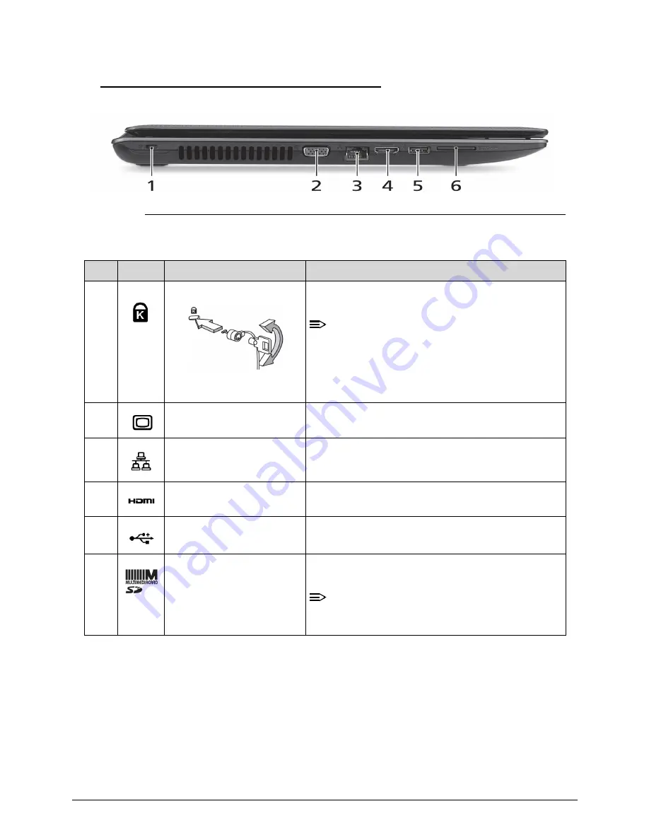
Left View
0
Figure 1-2. Left View
Table 1-2. Left View
No
Icon
Item
Description
1
Kensington lock slot
Connects to a Kensington-compatible computer
security lock.
NOTE:
Wrap the computer security lock cable around
an immovable object such as a table or handle
of a locked drawer. Insert the lock into the
notch and turn the key to secure the lock.
Some keyless models are also available.
2
External display (VGA)
port
Connects to a display device (e.g. external
monitor, LCD projector).
3
Ethernet (RJ-45) port
Connects to an Ethernet 10/100/1000-based
network.
4
HDMI port
Supports high-definition digital video connections.
5
USB 2.0 port
Connects to USB 2.0 devices (e.g., USB mouse,
USB camera).
6
2-in-1 card reader
Accepts Secure Digital (SD 3.0), MultiMediaCard
(MMC).
NOTE:
Push to remove/install the card. Only one card
can operate at any given time.
Summary of Contents for Aspire 7250
Page 36: ...1 40 Hardware Specifications and Configurations ...
Page 45: ...System Utilities 2 11 Figure 2 9 Setup Warning ...
Page 64: ...2 30 System Utilities ...
Page 71: ...3 11 Figure 3 7 HDD Module Figure 3 8 HDD Module 3 Remove HDD follow the arrowhead ...
Page 72: ...3 12 Figure 3 9 HDD Module Figure 3 10 HDD Module ...
Page 74: ...3 14 Figure 3 13 WLAN Module ...
Page 77: ...3 17 Figure 3 19 Memory Module Figure 3 20 Memory Module Figure 3 21 Memory Module ...
Page 85: ...3 25 Figure 3 35 TOP Case Figure 3 36 TOP Case ...
Page 88: ...3 28 Figure 3 42 I O BD Figure 3 43 I O BD ...
Page 90: ...3 30 Figure 3 46 Mother board Figure 3 47 Mother board 3 Take out the RTC battery ...
Page 91: ...3 31 Figure 3 48 RTC BATTERY Figure 3 49 RTC BATTERY ...
Page 93: ...3 33 Figure 3 51 Thermal Figure 3 52 Thermal ...
Page 101: ...3 41 Figure 3 68 LCD Panel Figure 3 69 LCD Panel 3 Put camera and MIC in the right place ...
Page 102: ...3 42 Figure 3 70 LCD Panel Figure 3 71 LCD Panel ...
Page 105: ...3 45 Figure 3 76 Hinge ...
Page 108: ...3 48 Figure 3 81 Main board Figure 3 82 Main board ...
Page 110: ...3 50 Figure 3 85 ODD BD Figure 3 86 ODD BD 2 Connect IO BD and ODD B D FFC CONN ...
Page 111: ...3 51 Figure 3 87 IO BD Figure 3 88 ODD BD ...
Page 114: ...3 54 Figure 3 93 Top case Figure 3 94 Top case ...
Page 116: ...3 56 Figure 3 97 Top case Figure 3 98 Top case Figure 3 99 Top case ...
Page 121: ...3 61 Figure 3 108 ...
Page 125: ...3 65 Figure 3 115 Battery ...
Page 126: ...3 66 ...
Page 152: ...4 28 Troubleshooting ...
Page 155: ...Jumper and Connector Locations 5 5 Figure 5 2 Mainboard Bottom ...
Page 160: ...5 10 Jumper and Connector Locations ...
Page 186: ...6 28 FRU Field Replaceable Unit List ...
Page 215: ...Test Compatible Components 8 11 ...
Page 216: ...8 12 Test Compatible Components ...
Page 217: ...Test Compatible Components 8 13 ...
Page 218: ...8 14 Test Compatible Components ...
Page 219: ...Test Compatible Components 8 15 ...
Page 220: ...8 16 Test Compatible Components ...
Page 221: ...Test Compatible Components 8 17 ...
Page 222: ...8 18 Test Compatible Components ...