


Chapter 2
41
BIOS Flash Utility
The BIOS flash memory update is required for the following conditions:
•
New versions of system programs
•
New features or options
•
Restore a BIOS when it becomes corrupted.
Use the Phlash utility to update the system BIOS flash ROM.
NOTE:
Create a
Crisis Recovery Media
(such as USB HDD) before you use the Phlash utility.
NOTE:
Do not install memory-related drivers (XMS, EMS, DPMI) when you use the Phlash.
NOTE:
Please use the AC adaptor power supply when you run the Phlash utility. If the battery pack does not
contain enough power to finish BIOS flash, the system will not boot as the BIOS is not loaded.
Perform the following steps to use the Flash Utility:
1.
Press F2 during boot to enter the Setup Menu.
2.
Select
Boot Menu
to modify the boot priority order, for example, if using USB HDD to Update BIOS, move
USB HDD to position 1.
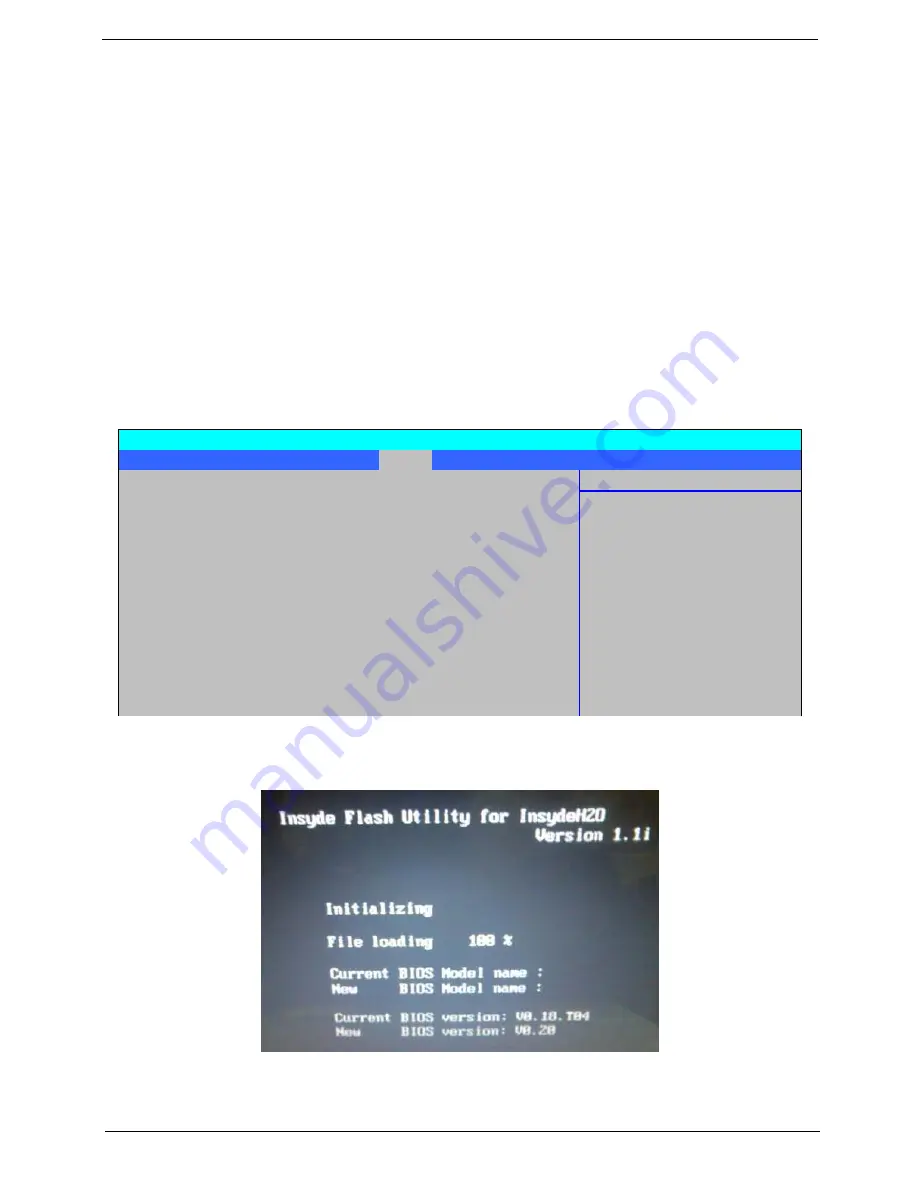
3.
Execute the
IFLASH.BAT
batch file to update BIOS (Read xxxxx.fd to Memory).
Information Main Security
Boot
Exit
Item Specific Help
Boot priority order:
1: USB HDD: ABC
Keys used to view or
2: IDE HDD: ST9320320AS
configure devices:
3: IDE CD: Optiarc BD ROM BC-5500S-(S
Up and Down arrows
4: PCI LAN: Atheros Boot Agent
select a device.
5: USB CDROM:
<> and <> moves
6: USB FDC:
the device up or down.
7: USB KEY:
<f> and <r> specifies
8:
the device fixed or
Excluded from boot order:
removable.
7
: IDE HDD: TOSHIBA MK3252GSX-(S5)
<x> exclude or include
Phoenix SecureCore(tm) Setup Utility
Summary of Contents for Aspire 6930 Series
Page 6: ...VI ...
Page 10: ...X Table of Contents ...
Page 42: ...32 Chapter 1 ...
Page 56: ...46 Chapter 2 ...
Page 91: ...Chapter 3 81 4 Grasp the module by the right side and lift up to remove ...
Page 99: ...Chapter 3 89 7 Disconnect the Mic cable and remove the LCD bezel ...
Page 110: ...100 Chapter 3 4 Replace the ten securing screws and screw caps on the LCD bezel ...
Page 112: ...102 Chapter 3 3 Connect fan cable to the mainboard as shown ...
Page 126: ...116 Chapter 3 7 Turn the computer over and replace the ten screws as shown ...
Page 234: ...224 Appendix B ...
Page 236: ...226 Appendix C ...
Page 239: ...www s manuals com ...