36
Chapter 2
Security
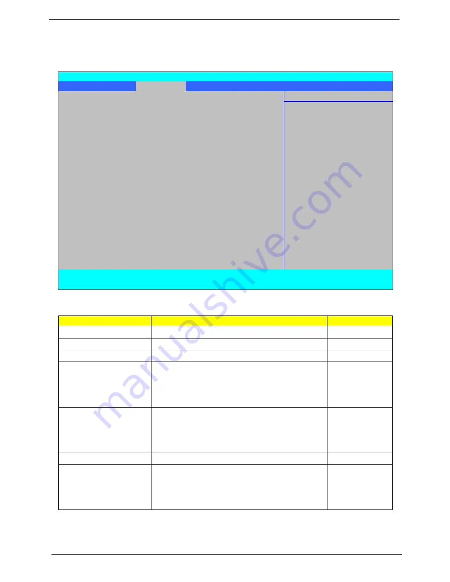
The Security screen contains parameters that help safeguard and protect your computer from unauthorized
use.
The table below describes the parameters in this screen. Settings in
boldface
are the default and suggested
parameter settings.
NOTE:
When you are prompted to enter a password, you have three tries before the system halts. Don’t forget
your password. If you forget your password, you may have to return your notebook computer to your
dealer to reset it.
Parameter
Description
Option
Supervisor Password Is
Shows the setting of the Supervisor password
Clear
or Set
User Password Is
Shows the setting of the user password.
Clear
or Set
HDD Password
Shows the setting of the hard disk password.
Clear
or Set
Set Supervisor Password
Press Enter to set the supervisor password. When
set, this password protects the BIOS Setup Utility
from unauthorized access. The user can not either
enter the Setup menu nor change the value of
parameters.
Set User Password
Press Enter to set the user password. When user
password is set, this password protects the BIOS
Setup Utility from unauthorized access. The user can
enter Setup menu only and does not have right to
change the value of parameters.
Set HDD Password
Enter HDD Password.
Password on Boot
Defines whether a password is required or not while
the events defined in this group happened. The
following sub-options are all requires the Supervisor
password for changes and should be grayed out if the
user password was used to enter setup.
Enabled or
Disabled
Information Main
Security
Boot
Exit
Item Specific Help
Supervisor Password Is:
Clear
User Password Is:
Clear
Supervisor Password
HDD Password
Clear
controls access to the
setup utility.
Set Supervisor Password
[Enter]
Set User Password
[Enter]
Set HDD Password
[Enter]
Password on Boot:
[Disabled]
F1
Help
↑↓
Select Item
F5/F6
Change Values
F9
Setup Defaults
ESC
Exit
←→
Select Menu
Enter
Select
X
Sub-Menu
F10
Save and Exit
Phoenix SecureCore(tm) Setup Utility
Summary of Contents for Aspire 6930 Series
Page 6: ...VI ...
Page 10: ...X Table of Contents ...
Page 42: ...32 Chapter 1 ...
Page 56: ...46 Chapter 2 ...
Page 91: ...Chapter 3 81 4 Grasp the module by the right side and lift up to remove ...
Page 99: ...Chapter 3 89 7 Disconnect the Mic cable and remove the LCD bezel ...
Page 110: ...100 Chapter 3 4 Replace the ten securing screws and screw caps on the LCD bezel ...
Page 112: ...102 Chapter 3 3 Connect fan cable to the mainboard as shown ...
Page 126: ...116 Chapter 3 7 Turn the computer over and replace the ten screws as shown ...
Page 234: ...224 Appendix B ...
Page 236: ...226 Appendix C ...
Page 239: ...www s manuals com ...


