70
Chapter 3
Removing the LCD Bezel
1.
See “Removing the Battery Pack” on page 42.
2.
See “Removing the Lower Cover” on page 43.
3.
See “Removing the Lower Cover” on page 43.
4.
See “Removing the Optical Drive Module” on page 44.
5.
See “Removing the DIMM” on page 45.
6.
See “Removing the Hard Disk Drive Module” on page 46.
7.
See “Removing the SSD Module” on page 48.
8.
See “Removing the RTC Battery” on page 48.
9.
See “Removing the Keyboard” on page 50.
10.
See “Removing the WLAN Board Module” on page 51.
11.
See “Separating the Upper Case from the Lower Case” on page 52.
12.
See “Removing the System Board” on page 58.
13.
See “Removing the LCD Module” on page 61.
14.
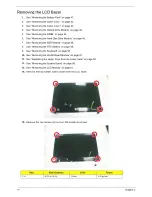
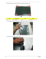
Remove the four rubber screw covers from the LCD bezel.
15.
Remove the four screws (G) on the LCD module as shown.
Step
Size (Quantity)
Color
Torque
1~4
M2.5 x L6 (4)
Silver
3.0 kgf-cm
Summary of Contents for Aspire 5810T Series
Page 6: ...VI...
Page 11: ...Chapter 1 3 Aspire 5810T 5810TZ 5410T System Block Diagram...
Page 12: ...4 Chapter 1 Aspire 5810TG System Block Diagram...
Page 17: ...Chapter 1 9 Rear View Icon Item Description 1 Battery bay Houses the computer s battery pack...
Page 46: ...38 Chapter 2...
Page 108: ...108 Chapter 6 Aspire 5810T 5810TZ 5410T Series Exploded Diagram...
Page 109: ...Chapter 6 109 Aspire 5810TG Series Exploded Diagram...
Page 131: ...Appendix A 117 Model Definition and Configuration Appendix A...
Page 142: ...Appendix A 128...
Page 146: ...132 Appendix B...
Page 148: ...134 Appendix C...
Page 152: ...138...


