


Chapter 2
25
Setting a Password
Follow these steps as you set the user or the supervisor password:
1.
Use the
↑
and
↓
keys to highlight the Set Supervisor Password parameter and press the
Enter
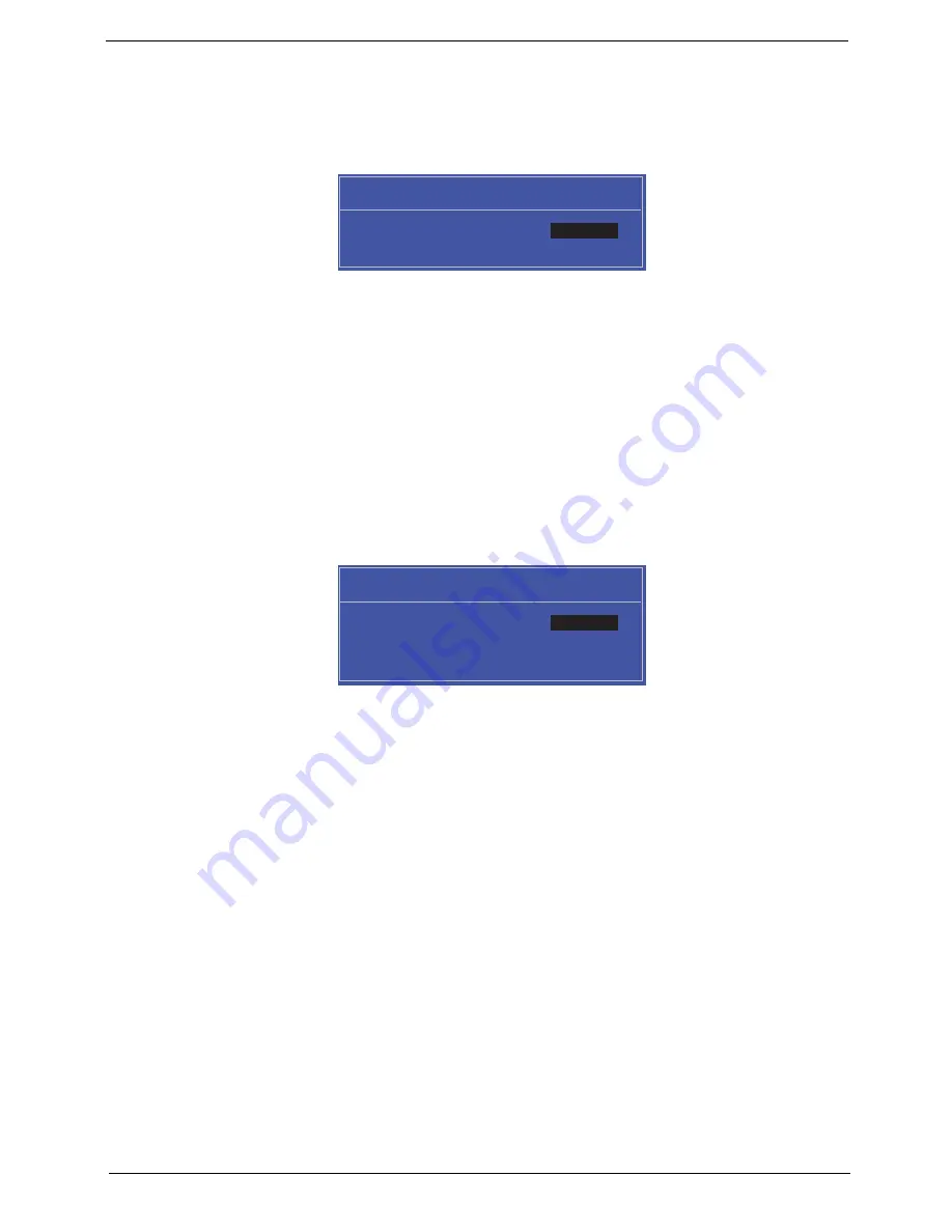
key. The
Set Supervisor Password box appears:
2.
Type a password in the “Enter New Password” field. The password length can not exceed 8 alphanumeric
characters (A-Z, a-z, 0-9, not case sensitive). Retype the password in the “Confirm New Password” field.
IMPORTANT:
Be very careful when typing your password because the characters do not appear on the screen.
3.
Press
Enter
.
After setting the password, the computer sets the User Password parameter to “Set”.
4.
If desired, you can opt to enable the Password on boot parameter.
5.
When you are done, press F10 to save the changes and exit the BIOS Setup Utility.
Removing a Password
Follow these steps:
1.
Use the
↑
and
↓
keys to highlight the Set Supervisor Password parameter and press the
Enter
key. The
Set Password box appears:
2.
Type the current password in the Enter Current Password field and press
Enter
.
3.
Press
Enter
twice
without
typing anything in the Enter New Password and Confirm New Password fields.
The computer then sets the Supervisor Password parameter to “Clear”.
4.
When you have changed the settings, press
u
to save the changes and exit the BIOS Setup Utility.
S e t S u p e r v i s o r P a s s w o r d
E n t e r N e w P a s s w o r d [ ]
[ ]
C o n f i r m N e w P a s s w o r d [ ]
S e t S u p e r v i s o r P a s s w o r d
E n t e r C u r r e n t P a s s w o r d [ ]
[ ]
E n t e r N e w P a s s w o r d [ ]
C o n f i r m N e w P a s s w o r d [ ]
[ ]
Summary of Contents for Aspire 5741
Page 6: ...VI ...
Page 10: ...X Table of Contents ...
Page 15: ...Chapter 1 5 System Block Diagram ...
Page 48: ...38 Chapter 2 ...
Page 72: ...62 Chapter 3 5 Lift the Speaker clear of the Upper Cover ...
Page 74: ...64 Chapter 3 5 Lift the Right Speaker Module clear of the device ...
Page 86: ...76 Chapter 3 4 Carefully lift the Thermal Module clear of the Mainboard ...
Page 95: ...Chapter 3 85 5 Lift the LCD Panel clear of the module ...
Page 98: ...88 Chapter 3 7 Disconnect the LVDS cable from the panel ...
Page 100: ...90 Chapter 3 5 Lift the microphone set clear of the panel ...
Page 118: ...108 Chapter 3 6 Connect the LVDS cable and lock the connector 7 Connect the microphone cable ...
Page 123: ...Chapter 3 113 4 Replace the FFC and press down as indicated to secure it to the Upper Cover ...
Page 169: ...Chapter 6 159 10 LCD Cover 60 PSV02 003 No Description Acer P N ...
Page 179: ...Chapter 6 169 ...
Page 180: ...Appendix A 170 Model Definition and Configuration Appendix A ...
Page 252: ...242 Appendix B ...
Page 254: ...244 Appendix C ...
Page 258: ...248 ...