


24
Chapter 2
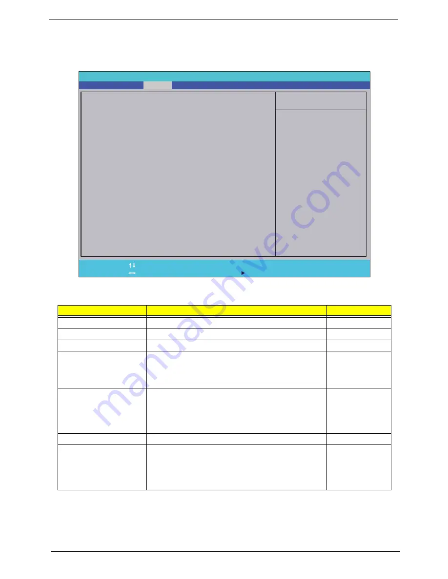
Security
The Security screen contains parameters that help safeguard and protect your computer from unauthorized
use.
The table below describes the parameters in this screen. Settings in
boldface
are the default and suggested
parameter settings.
NOTE:
When you are prompted to enter a password, you have three tries before the system halts. Don’t forget
your password. If you forget your password, you may have to return your notebook computer to your
dealer to reset it.
Parameter
Description
Option
Supervisor Password Is
Shows the setting of the Supervisor password
Clear
or Set
User Password Is
Shows the setting of the user password.
Clear
or Set
HDD0 Password Is
Shows the setting of the hard disk password.
Clear
or Set
Set Supervisor Password
Press Enter to set the supervisor password. When set,
this password protects the BIOS Setup Utility from
unauthorized access. The user can not either enter the
Setup menu nor change the value of parameters.
N/A
Set User Password
Press Enter to set the user password. When user
password is set, this password protects the BIOS Setup
Utility from unauthorized access. The user can enter
Setup menu only and does not have right to change the
value of parameters.
N/A
Set HDD Password
Enter HDD Password.
N/A
Password on Password
Defines whether a password is required or not while the
events defined in this group happened. The following
sub-options are all requires the Supervisor password
for changes and should be grayed out if the user
password was used to enter setup.
Disabled
or
Enabled
I t e m S p e c i f i c H e l p
I n s t a l l o r C h a n g e t h e
p a s s w o r d a n d t h e l e n g t h
o f p a s s w o r d m u s t b e l e s s
t h a n e i g h t w o r d s .
F 1
E S C
H e l p
E x i t
S e l e c t I t e m
S e l e c t M e n u
C h a n g e Va l u e s
S e l e c t
S u b M e n u
E n t e r
F 9
F 1 0
S e t u p D e f a u l t
S a v e a n d E x i t
C l e a r
C l e a r
C l e a r
[ E n a b l e d ]
C l e a r
C l e a r
C l e a r
[ E n a b l e d ]
S u p e r v i s o r P a s s w o r d I s :
U s e r P a s s w o r d I s :
H D D P a s s w o r d I s :
S e t S u p e r v i s o r P a s s w o r d
S e t U s e r P a s s w o r d
S e t H D D 0 P a s s w o r d
P a s s w o r d o n P a s s w o r d
S u p e r v i s o r P a s s w o r d I s :
U s e r P a s s w o r d I s :
H D D P a s s w o r d I s :
S e t S u p e r v i s o r P a s s w o r d
S e t U s e r P a s s w o r d
S e t H D D 0 P a s s w o r d
P a s s w o r d o n P a s s w o r d
F 5 / F 6
I n s y d e H 2 0 S e t u p U t i l i t y R e v . 3 . 5
Information
Main
Boot
Exit
Security
Summary of Contents for Aspire 5741
Page 6: ...VI ...
Page 10: ...X Table of Contents ...
Page 15: ...Chapter 1 5 System Block Diagram ...
Page 48: ...38 Chapter 2 ...
Page 72: ...62 Chapter 3 5 Lift the Speaker clear of the Upper Cover ...
Page 74: ...64 Chapter 3 5 Lift the Right Speaker Module clear of the device ...
Page 86: ...76 Chapter 3 4 Carefully lift the Thermal Module clear of the Mainboard ...
Page 95: ...Chapter 3 85 5 Lift the LCD Panel clear of the module ...
Page 98: ...88 Chapter 3 7 Disconnect the LVDS cable from the panel ...
Page 100: ...90 Chapter 3 5 Lift the microphone set clear of the panel ...
Page 118: ...108 Chapter 3 6 Connect the LVDS cable and lock the connector 7 Connect the microphone cable ...
Page 123: ...Chapter 3 113 4 Replace the FFC and press down as indicated to secure it to the Upper Cover ...
Page 169: ...Chapter 6 159 10 LCD Cover 60 PSV02 003 No Description Acer P N ...
Page 179: ...Chapter 6 169 ...
Page 180: ...Appendix A 170 Model Definition and Configuration Appendix A ...
Page 252: ...242 Appendix B ...
Page 254: ...244 Appendix C ...
Page 258: ...248 ...