


8
Chapter 1
Right View
4
Ethernet (RJ-45)
port
Connects to an Ethernet 10/100/1000-based
network.
5
HDMI
Connect to HDMI devices
6
USB 2.0 ports
Connect to USB 2.0 devices (e.g. USB mouse,
USB camera).
7
Microphone-in
jack
Accepts input from external microphones.
Headphones/
speaker/line-out
jack
Connects to audio line-out devices
(e.g. speakers, headphones).
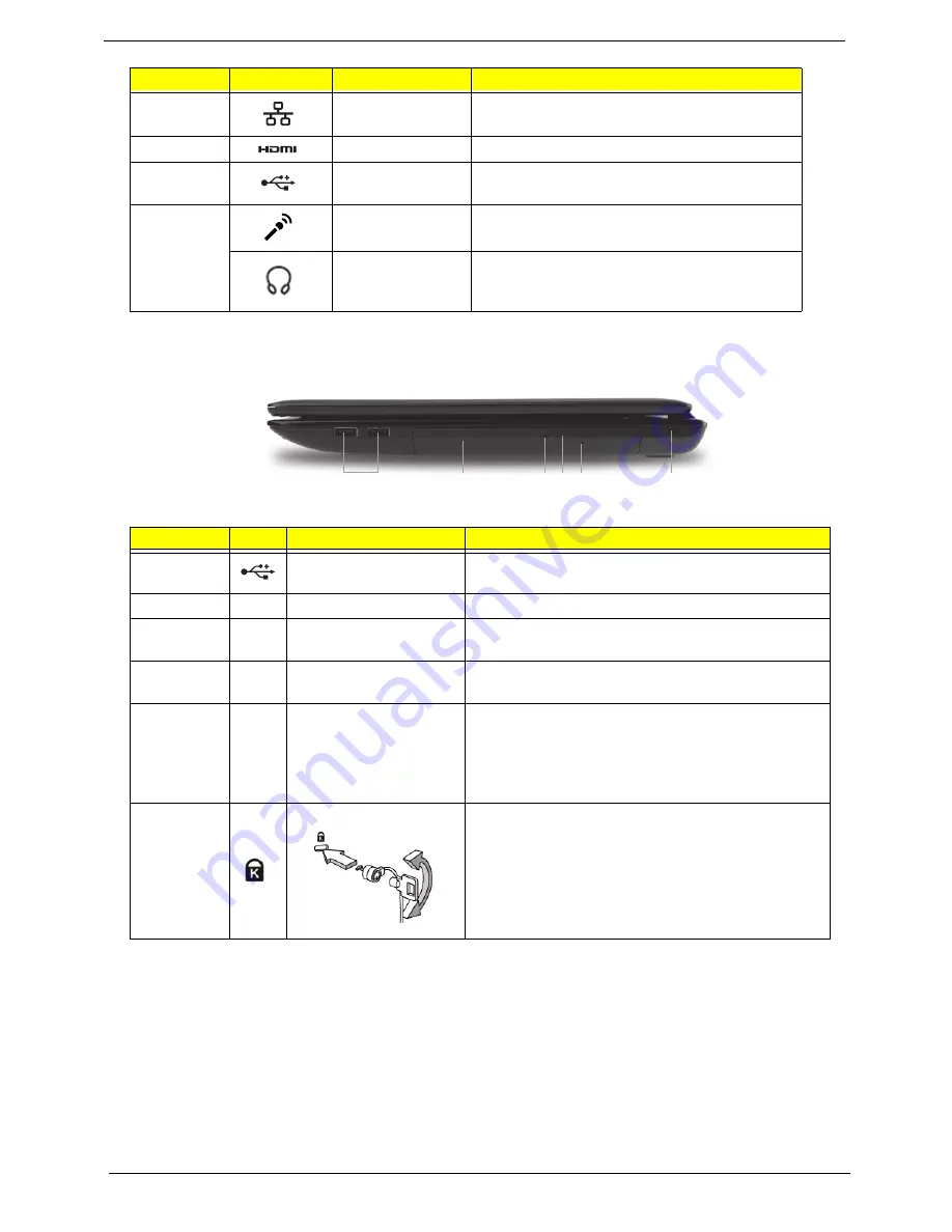
No.
Icon
Item
Description
1
USB 2.0 ports
Connect to USB 2.0 devices (e.g. USB mouse, USB
camera).
2
Optical drive
Internal optical drive; accepts CDs or DVDs.
3
Optical disk access
indicator
Lights up when the optical drive is active.
4
Optical drive eject
button
Ejects the optical disk from the drive.
5
Emergency eject hole
Ejects the optical drive tray when the computer is
turned off.
Note:
Insert a paper clip into the emergency eject
hole to eject the optical drive tray when the computer
is off.
6
Kensington lock slot
Connects to a Kensington-compatible computer
security lock.
Note:
Wrap the computer security lock cable around
an immovable object such as a table or handle of a
locked drawer. Insert the lock into the notch and turn
the key to secure the lock. Some keyless models are
also available.
No.
Icon
Item
Description
1
2
3 4 5
6
Summary of Contents for Aspire 5741
Page 6: ...VI ...
Page 10: ...X Table of Contents ...
Page 15: ...Chapter 1 5 System Block Diagram ...
Page 48: ...38 Chapter 2 ...
Page 72: ...62 Chapter 3 5 Lift the Speaker clear of the Upper Cover ...
Page 74: ...64 Chapter 3 5 Lift the Right Speaker Module clear of the device ...
Page 86: ...76 Chapter 3 4 Carefully lift the Thermal Module clear of the Mainboard ...
Page 95: ...Chapter 3 85 5 Lift the LCD Panel clear of the module ...
Page 98: ...88 Chapter 3 7 Disconnect the LVDS cable from the panel ...
Page 100: ...90 Chapter 3 5 Lift the microphone set clear of the panel ...
Page 118: ...108 Chapter 3 6 Connect the LVDS cable and lock the connector 7 Connect the microphone cable ...
Page 123: ...Chapter 3 113 4 Replace the FFC and press down as indicated to secure it to the Upper Cover ...
Page 169: ...Chapter 6 159 10 LCD Cover 60 PSV02 003 No Description Acer P N ...
Page 179: ...Chapter 6 169 ...
Page 180: ...Appendix A 170 Model Definition and Configuration Appendix A ...
Page 252: ...242 Appendix B ...
Page 254: ...244 Appendix C ...
Page 258: ...248 ...