


238
Appendix B
"LED 2nd
source(IPE
X
compatible)
H-CONN SET 0C9
LED LCD-M/B W/
CAMERA 2nd
source(IPEX
compatible)
MEC
LED w/o CMOS
H-CONN SET 0C9 LED LCD-M/B W/O
CAMERA
"MEC
""LED w/o
CMOS
"H-CONN
SET 0C9
LED LCD-
M/B W/O
CAMERA
MEC
LED With 3G
H-CONN SET 0C9 LED LCD-MB W/CAM
W/3G H_C
"MEC
""LED With
3G
"H-CONN
SET 0C9
LED LCD-
MB W/CAM
W/3G H_C
MEC
LED w/o CMOS With
3G
H-CONN SET 0C9 LED LCD-MB WOCAM
W/3G H_C
"MEC
""LED w/o
CMOS With
3G
"H-CONN
SET 0C9
LED LCD-
MB
WOCAM
W/3G H_C
"MEC
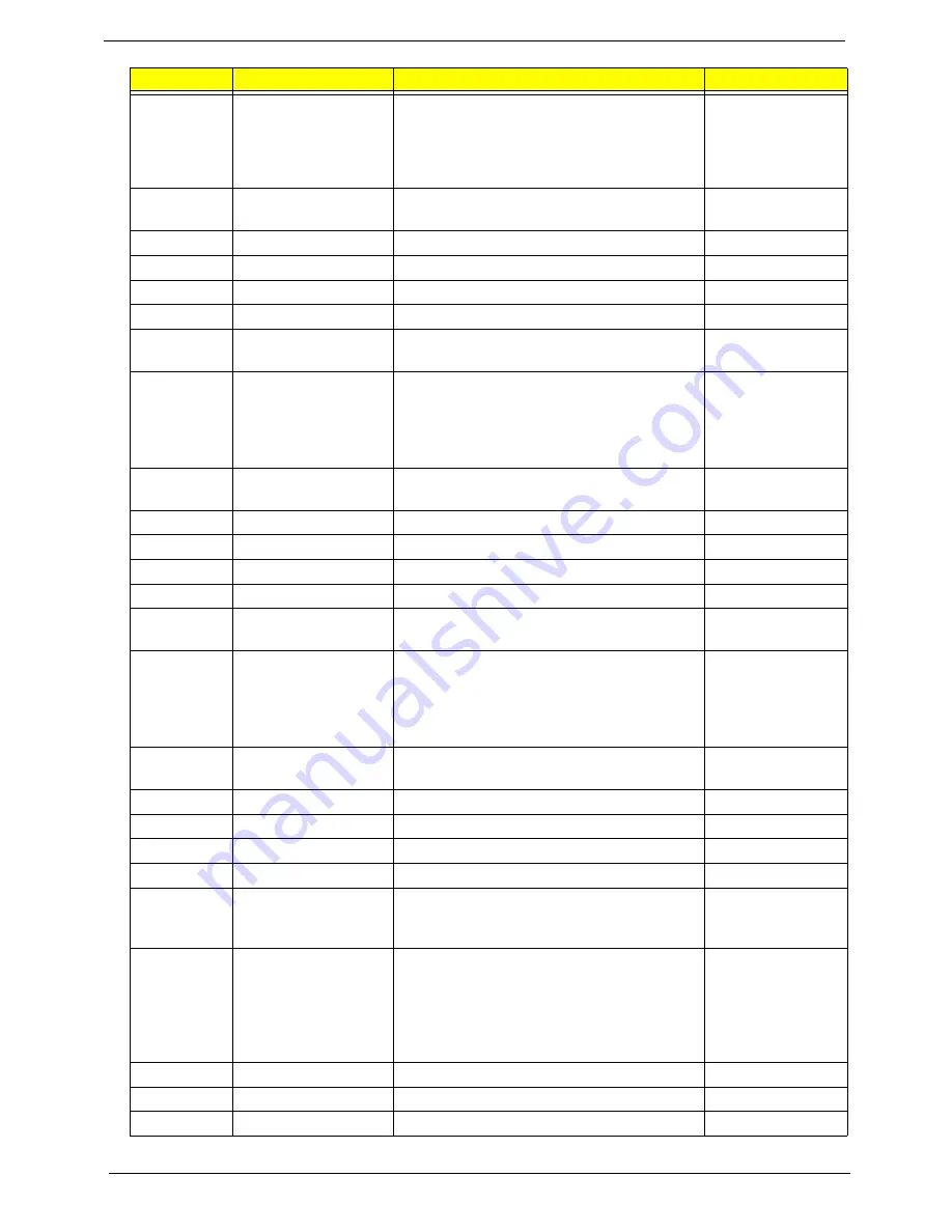
Vendor
Type
Description
PN
Summary of Contents for Aspire 5741
Page 6: ...VI ...
Page 10: ...X Table of Contents ...
Page 15: ...Chapter 1 5 System Block Diagram ...
Page 48: ...38 Chapter 2 ...
Page 72: ...62 Chapter 3 5 Lift the Speaker clear of the Upper Cover ...
Page 74: ...64 Chapter 3 5 Lift the Right Speaker Module clear of the device ...
Page 86: ...76 Chapter 3 4 Carefully lift the Thermal Module clear of the Mainboard ...
Page 95: ...Chapter 3 85 5 Lift the LCD Panel clear of the module ...
Page 98: ...88 Chapter 3 7 Disconnect the LVDS cable from the panel ...
Page 100: ...90 Chapter 3 5 Lift the microphone set clear of the panel ...
Page 118: ...108 Chapter 3 6 Connect the LVDS cable and lock the connector 7 Connect the microphone cable ...
Page 123: ...Chapter 3 113 4 Replace the FFC and press down as indicated to secure it to the Upper Cover ...
Page 169: ...Chapter 6 159 10 LCD Cover 60 PSV02 003 No Description Acer P N ...
Page 179: ...Chapter 6 169 ...
Page 180: ...Appendix A 170 Model Definition and Configuration Appendix A ...
Page 252: ...242 Appendix B ...
Page 254: ...244 Appendix C ...
Page 258: ...248 ...