


76
Chapter 3
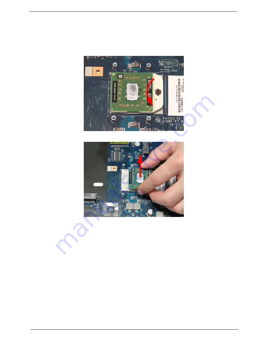
Removing the CPU
IMPORTANT:
The pins on the underside of the CPU are very delicate. If they are damaged, the CPU may
malfunction. Place the CPU on a clean, dry surface when it is not installed.
1.
See “Removing the Thermal Module” on page 72.
2.
Using a flat-bladed screw driver, rotate the CPU locking screw 180° counter-clockwise as shown.
3.
Lift the CPU clear of the socket as shown.
Summary of Contents for ASPIRE 5532
Page 6: ...VI ...
Page 10: ...X Table of Contents ...
Page 14: ...4 Chapter 1 System Block Diagram ...
Page 32: ...22 Chapter 1 General Features PCI E interface Push push type Dummy card Item Specification ...
Page 70: ...60 Chapter 3 4 Disconnect the following four 4 cables from the Mainboard A B C D ...
Page 83: ...Chapter 3 73 4 Using both hands lift the Thermal Module clear of the Mainboard ...
Page 85: ...Chapter 3 75 4 Lift the CPU Fan clear of the Mainboard as shown ...
Page 91: ...Chapter 3 81 5 Lift the LCD Panel clear of the module ...
Page 99: ...Chapter 3 89 9 The Antennas and cables appear as shown when correctly installed ...
Page 104: ...94 Chapter 3 2 Replace the four 4 screws and screw caps provided ...
Page 109: ...Chapter 3 99 5 Replace the FFC and press down as indicated to secure it to the Upper Cover ...
Page 120: ...110 Chapter 3 17 Replace the two 2 screws securing the LCD Module to the Lower Cover ...
Page 128: ...118 Chapter 3 ...
Page 152: ...142 Chapter 5 ...
Page 154: ...144 Chapter 6 Aspire 5532 Exploded Diagrams Main Assembly 1 2 3 4 5 ...
Page 165: ...Chapter 6 155 ...
Page 180: ...Appendix A 170 ...
Page 198: ...188 Appendix C ...
Page 202: ...192 ...
Page 203: ...www s manuals com ...