


114
Chapter 3
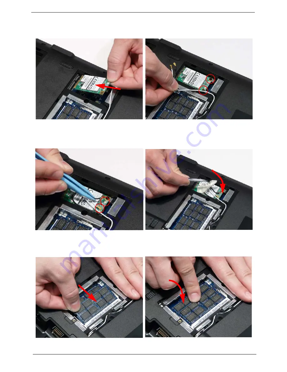
Replacing the WLAN Module
Replacing the DIMM Modules
1.
Insert the WLAN Module into the WLAN socket.
2.
Replace the two (2) screws to secure the module.
3.
Connect the two (2) Antenna cables to the module.
NOTE:
The black cable connects to the upper
terminal (MAIN) and the white cable to the
lower terminal (MAIN).
4.
After connecting the cables to the terminals,
secure the cables in place with adhesive tape to
avoid trapping.
1.
Insert the DIMM Module in place.
2.
Press down to lock the DIMM module in place.
3.
Repeat steps for the second DIMM module if present.
Summary of Contents for ASPIRE 5532
Page 6: ...VI ...
Page 10: ...X Table of Contents ...
Page 14: ...4 Chapter 1 System Block Diagram ...
Page 32: ...22 Chapter 1 General Features PCI E interface Push push type Dummy card Item Specification ...
Page 70: ...60 Chapter 3 4 Disconnect the following four 4 cables from the Mainboard A B C D ...
Page 83: ...Chapter 3 73 4 Using both hands lift the Thermal Module clear of the Mainboard ...
Page 85: ...Chapter 3 75 4 Lift the CPU Fan clear of the Mainboard as shown ...
Page 91: ...Chapter 3 81 5 Lift the LCD Panel clear of the module ...
Page 99: ...Chapter 3 89 9 The Antennas and cables appear as shown when correctly installed ...
Page 104: ...94 Chapter 3 2 Replace the four 4 screws and screw caps provided ...
Page 109: ...Chapter 3 99 5 Replace the FFC and press down as indicated to secure it to the Upper Cover ...
Page 120: ...110 Chapter 3 17 Replace the two 2 screws securing the LCD Module to the Lower Cover ...
Page 128: ...118 Chapter 3 ...
Page 152: ...142 Chapter 5 ...
Page 154: ...144 Chapter 6 Aspire 5532 Exploded Diagrams Main Assembly 1 2 3 4 5 ...
Page 165: ...Chapter 6 155 ...
Page 180: ...Appendix A 170 ...
Page 198: ...188 Appendix C ...
Page 202: ...192 ...
Page 203: ...www s manuals com ...