


50
Chapter 3
External Modules Disassembly Process
IMPORTANT:
The outside housing and color may vary from the mass produced model.
External Modules Disassembly Flowchart
The flowchart below gives you a graphic representation on the entire disassembly sequence and instructs you on
the components that need to be removed during servicing. For example, if you want to remove the mainboard, you
must first remove the keyboard, then disassemble the inside assembly frame in that order.
Screw List
Step
Screw
Quantity
Part No.
ODD Module
Disassembly
M2.5*6.5-I
1
86.ARE07.001
ODD Bracket
Disassembly
M2.0*3.0-I
2
86.ARE07.002
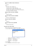
Summary of Contents for ASPIRE 4252
Page 6: ...VI ...
Page 10: ...X Table of Contents ...
Page 56: ...46 Chapter 2 ...
Page 103: ...Chapter 3 93 3 Connect the speaker cable to the mainboard ...
Page 106: ...96 Chapter 3 5 Connect the fan cable as shown ...
Page 112: ...102 Chapter 3 Step Size Quantity Screw Type HDD Module M2 5 3 0 Ni 2 ...
Page 174: ...164 Appendix B ...
Page 176: ...166 Appendix C ...


