


Chapter 3
63
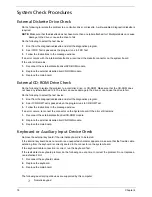
Disassembly Procedure Flowchart
The flowchart on the succeeding page gives you a graphic representation on the entire disassembly sequence
and instructs you on the components that need to be removed during servicing. For example, if you want to
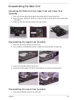
remove the system board, you must first remove the keyboard, then disassemble the inside assembly frame in
that order.
Start
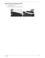
Battery
Middle Cover
HDD Cover
DIMM Cover
H*2
P*1
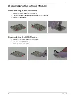
HDD Module
O*4
H*3
CPU
Lower Case
Assembly
86.9A353.3R0*2
Modem Board
Memory
ODD Module
Wireless LAN
Card
HDD
HDD Bracket
M*4
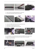
Keyboard
LCD Module
J*2 on bottom side
K*2 on top side
E*1 on upper case assemby
E*12 on bottom side
F*3 on bottom side
A*2 on rear side
Upper Case
Assembly
N*3
Upper Case
Touchpad
Assembly
Touchpad
Bracket
Touchpad
Lower Case
Main Board
Assembly
Speaker Set
CPU Heatsink
C*1
D*2
RTC Battery
Bluetooth
Module
ODD Module
G*2
ODD
ODD Bracket
E*1
Microphone
North Bridge
Plate
86.9A353.3R0*2
*2
O*2
O*2
Fan
Summary of Contents for Aspire 3050
Page 6: ...VI...
Page 31: ...Chapter 1 23...
Page 67: ...Chapter 2 59...
Page 68: ...60 Chapter 2...
Page 79: ...Chapter 3 71...
Page 96: ...88 Chapter 4 F5h Boot to Mini DOS F6h Clear Huge Segment F7h Boot to Full DOS Code Beeps...
Page 106: ...98 Chapter 5...
Page 108: ...100 Chapter 6 Aspire 5050 3050 Exploded Diagram...
Page 152: ...144 Appendix B...
Page 154: ...146 Appendix C...
Page 157: ...Index 149...