


26
Chapter 2
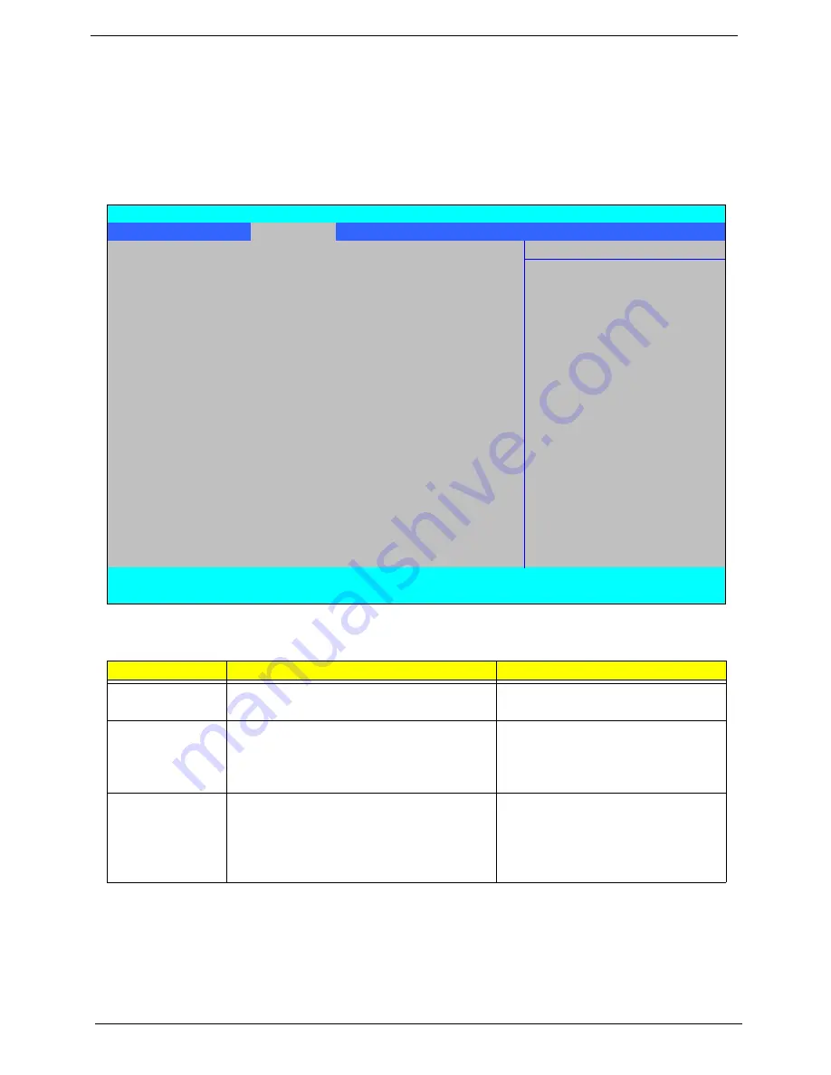
Advanced
The Advanced screen allows the user to configure the various advanced BIOS options.
IMPORTANT:
Making incorrect settings to items on these pages may cause the system to malfunction. Unless
you have experience adjusting these items, we recommend that you leave these settings at the
default values. If making settings to items on these pages causes your system to malfunction or
prevents the system from booting, open BIOS and choose Load Optimal Defaults in the Exit menu to
boot up normally.
The table below describes the items, menus, and submenus in this screen. Settings in
boldface
are the default
and suggested parameter settings.
Parameter
Description
Submenu Items
Boot
Configuration
Enter the Boot Configuration menu.
•
Numlock
•
Zip Emulation Type
Peripheral
Configuration
Enter the Peripheral Configuration menu.
•
Serial Port A
•
Infrared Port
•
Azalia
•
LAN
IDE
Configuration
Enter the IDE Configuration menu.
•
IDE Controller
•
HDC Configure as
•
ACHI Option ROM Support
•
SATA Port 0, 1, 4, and 5 Hotplug
•
Channel 1 to 4 Master and Slave
InsydeH20 Setup Utility
Rev. 3.5
Information Main
Advanced
Security
Power
Boot
Exit
Item Specific Help
X
Boot Configuration
Configures Boot
X
Peripheral Configuration
Settings.
X
IDE Configuration
X
Video Configuration
X
USB Configuration
X
Chipset Configuration
X
ACPI Table/Features Control
Express Card
[Disabled]
X
PCI Express Root Port 1
X
PCI Express Root Port 2
X
PCI Express Root Port 3
X
PCI Express Root Port 4
X
PCI Express Root Port 5
X
PCI Express Root Port 6
X
ASF Configuration
F1
Help
↑↓
Select Item
F5/F6
Change Values
F9
Setup Default
ESC
Exit
←→
Select Menu
Enter
Select
X
SubMenu
F10
Save and Exit
Summary of Contents for Aspire 2430
Page 6: ...VI ...
Page 10: ...X Table of Contents ...
Page 32: ...22 Chapter 1 ...
Page 59: ...Chapter 3 49 5 Detach the WLAN board from the WLAN socket ...
Page 71: ...Chapter 3 61 5 Remove both Speaker Modules ...
Page 73: ...Chapter 3 63 7 Place the computer rightside up and remove the cables from the housing ...
Page 83: ...Chapter 3 73 4 Grasp the left side of the bracket and angle upwards to remove ...
Page 89: ...Chapter 3 79 5 Lift the module from the mainboard ...
Page 101: ...Chapter 3 91 5 Disconnect the left and right Inverter board cables as shown ...
Page 117: ...Chapter 3 107 6 Replace the three securing screws ...
Page 134: ...124 Chapter 3 ...
Page 156: ...146 Chapter 4 ...
Page 173: ...Chapter 6 163 ...
Page 238: ...Appendix A 228 ...
Page 244: ...234 Appendix B ...
Page 246: ...236 Appendix C ...
Page 249: ...239 Wireless Function Failure 138 WLAN Board 48 ...
Page 250: ...240 ...