


10
Chapter 1
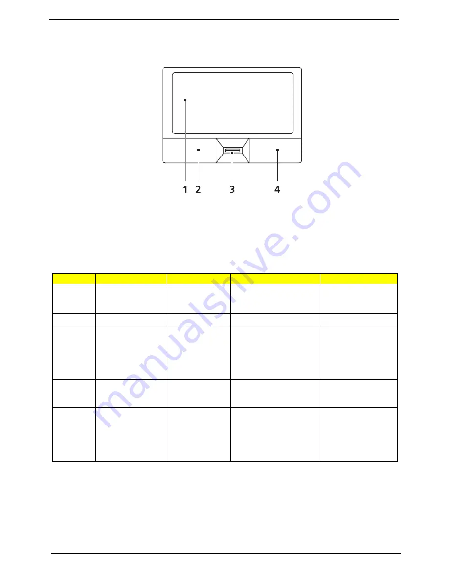
Touch Pad Basics (with fingerprint reader)
The following items show you how to use the Touch Pad with Acer Bio-Protection fingerprint reader:
•
Move your finger across the touchpad (1) to move the cursor.
•
Press the left (2) and right (4) buttons located beneath the touchpad to perform selection and
execution functions. These two buttons are similar to the left and right buttons on a mouse.
Tapping on the touchpad is the same as clicking the left button.
•
Use Acer Bio-Protection fingerprint reader (3) supporting Acer FingerNav 4-way control function
(only for certain models) to scroll up or down and move left or right a page. This fingerprint reader
or button mimics your cursor pressing on the right scroll bar of Windows applications.
NOTE:
When using the Touch Pad, keep it - and your fingers - dry and clean. The Touch Pad is sensitive to
finger movement; hence, the lighter the touch, the better the response. Tapping too hard will not
increase the Touch Pad’s responsiveness.
Function
Left Button (2)
Right Button (4)
Main Touch Pad (1)
Center button (3)
Execute
Quickly click twice.
Tap twice (at the same
speed as double-clicking
a mouse button).
Select Click
once.
Tap
once.
Drag
Click and hold,
then use finger on
the touchpad to
drag the cursor.
Tap twice (at the same
speed as double-clicking
a mouse button); rest
your finger on the
touchpad on the second
tap and drag the cursor.
Access
context
menu
Click once.
Scroll
Swipe up/down/left/
right using Acer
FingerNav 4-way
control function
(Manufacturing
option).
Summary of Contents for Aspire 2430
Page 6: ...VI ...
Page 10: ...X Table of Contents ...
Page 32: ...22 Chapter 1 ...
Page 59: ...Chapter 3 49 5 Detach the WLAN board from the WLAN socket ...
Page 71: ...Chapter 3 61 5 Remove both Speaker Modules ...
Page 73: ...Chapter 3 63 7 Place the computer rightside up and remove the cables from the housing ...
Page 83: ...Chapter 3 73 4 Grasp the left side of the bracket and angle upwards to remove ...
Page 89: ...Chapter 3 79 5 Lift the module from the mainboard ...
Page 101: ...Chapter 3 91 5 Disconnect the left and right Inverter board cables as shown ...
Page 117: ...Chapter 3 107 6 Replace the three securing screws ...
Page 134: ...124 Chapter 3 ...
Page 156: ...146 Chapter 4 ...
Page 173: ...Chapter 6 163 ...
Page 238: ...Appendix A 228 ...
Page 244: ...234 Appendix B ...
Page 246: ...236 Appendix C ...
Page 249: ...239 Wireless Function Failure 138 WLAN Board 48 ...
Page 250: ...240 ...