


Chapter 1
11
Using the Keyboard
The keyboard has full-sized keys and an embedded numeric keypad, separate cursor, lock, Windows, function
and special keys.
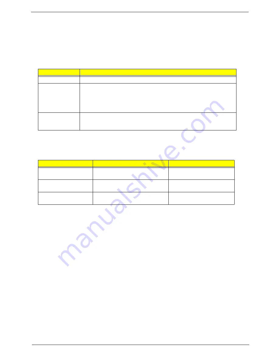
Lock Keys and embedded numeric keypad
The keyboard has three lock keys which you can toggle on and off.
The embedded numeric keypad functions like a desktop numeric keypad. It is indicated by small characters
located on the upper right corner of the keycaps. To simplify the keyboard legend, cursor-control key symbols
are not printed on the keys.
Lock key
Description
Caps Lock
When Caps Lock is on, all alphabetic characters typed are in uppercase.
Num Lock
<Fn> + <F11>
When Num Lock is on, the embedded keypad is in numeric mode. The keys
function as a calculator (complete with the arithmetic ope, -, *, and /). Use
this mode when you need to do a lot of numeric data entry. A better solution
would be to connect an external keypad.
Note:
<Fn>
+
<F11>
only for certain models.
Scroll Lock
<Fn> +
<F12>
When Scroll Lock is on, the screen moves one line up or down when you press
the up or down arrow keys respectively. Scroll Lock does not work with some
applications.
Desired access
Num Lock on
Num Lock off
Number keys on
embedded keypad
Type numbers in a normal manner.
Cursor-control keys on
embedded keypad
Hold
<Shift>
while using cursor-
control keys.
Hold
<Fn>
while using cursor-
control keys.
Main keyboard keys
Hold
<Fn>
while typing letters on
embedded keypad.
Type the letters in a normal
manner.
Summary of Contents for Aspire 2430
Page 6: ...VI ...
Page 10: ...X Table of Contents ...
Page 32: ...22 Chapter 1 ...
Page 59: ...Chapter 3 49 5 Detach the WLAN board from the WLAN socket ...
Page 71: ...Chapter 3 61 5 Remove both Speaker Modules ...
Page 73: ...Chapter 3 63 7 Place the computer rightside up and remove the cables from the housing ...
Page 83: ...Chapter 3 73 4 Grasp the left side of the bracket and angle upwards to remove ...
Page 89: ...Chapter 3 79 5 Lift the module from the mainboard ...
Page 101: ...Chapter 3 91 5 Disconnect the left and right Inverter board cables as shown ...
Page 117: ...Chapter 3 107 6 Replace the three securing screws ...
Page 134: ...124 Chapter 3 ...
Page 156: ...146 Chapter 4 ...
Page 173: ...Chapter 6 163 ...
Page 238: ...Appendix A 228 ...
Page 244: ...234 Appendix B ...
Page 246: ...236 Appendix C ...
Page 249: ...239 Wireless Function Failure 138 WLAN Board 48 ...
Page 250: ...240 ...