


6
Chapter 1
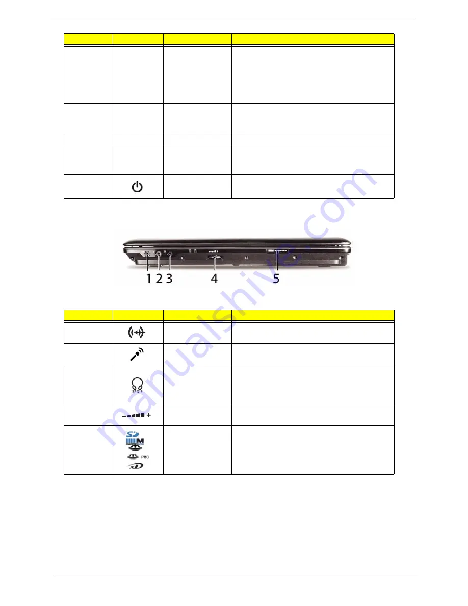
Closed Front View
9
Click buttons
(left, center* and
right)
The left and right buttons function like the left
and right mouse buttons.
*The center button serves as Acer Bio-
Protection fingerprint reader supporting Acer
FingerNav 4-way control function (only for
certain models).
10
Status indicators
Light-Emitting Diodes (LEDs) that light up to
show the status of the computer's functions
and components.
11
Keyboard
For entering data into your computer.
12
Status indicators
Light-Emitting Diodes (LEDs) that light up to
show the status of the computer's functions
and components.
13
Power button
Turns the computer on and off.
No.
Icon
Item
Description
1
Line-in jack
Accepts audio line-in devices (e.g. audio CD
player, stereo walkman, mp3 player).
2
Microphone-in
jack
Accepts input from external microphones.
3
Headphones/
speaker/line-out
jack with S/PDIF
support
Connects to audio line-out devices
(e.g. speakers, headphones).
4
Unlimited volume
control wheel
Adjust the volume of the audio-out.
5
5-in-1 card
reader
Accepts Secure Digital (SD), MultiMediaCard
(MMC), Memory Stick (MS), Memory Stick Pro
(MS PRO), xD-Picture Card.
Note:
Push to remove/install the card. Only
one card can operate at any given time.
No.
Icon
Item
Description
Summary of Contents for Aspire 2430
Page 6: ...VI ...
Page 10: ...X Table of Contents ...
Page 32: ...22 Chapter 1 ...
Page 59: ...Chapter 3 49 5 Detach the WLAN board from the WLAN socket ...
Page 71: ...Chapter 3 61 5 Remove both Speaker Modules ...
Page 73: ...Chapter 3 63 7 Place the computer rightside up and remove the cables from the housing ...
Page 83: ...Chapter 3 73 4 Grasp the left side of the bracket and angle upwards to remove ...
Page 89: ...Chapter 3 79 5 Lift the module from the mainboard ...
Page 101: ...Chapter 3 91 5 Disconnect the left and right Inverter board cables as shown ...
Page 117: ...Chapter 3 107 6 Replace the three securing screws ...
Page 134: ...124 Chapter 3 ...
Page 156: ...146 Chapter 4 ...
Page 173: ...Chapter 6 163 ...
Page 238: ...Appendix A 228 ...
Page 244: ...234 Appendix B ...
Page 246: ...236 Appendix C ...
Page 249: ...239 Wireless Function Failure 138 WLAN Board 48 ...
Page 250: ...240 ...