


Chapter 4
133
No Display Issue
If the Display doesn’t work, perform the following actions one at a time to correct the problem. Do not replace
non-defective FRUs:
No POST or Video
If the POST or video doesn’t display, perform the following actions one at a time to correct the problem.
1.
Make sure that the internal display is selected. On this notebook model, switching between the internal
display and the external display is done by pressing Fn+F5. Reference Product pages for specific model
procedures.
2.
Make sure the computer has power by checking at least one of the following occurs:
•
Fans start up
•
Status LEDs light up
If there is no power, see “Power On Issue” on page 132.
3.
Drain any stored power by removing the power cable and battery and holding down the power button for
10 seconds. Reconnect the power and reboot the computer.
4.
Connect an external monitor to the computer and switch between the internal display and the external
display is by pressing Fn+F5 (on this model).
If the POST or video appears on the external display, see “LCD Failure” on page 135.
5.
Disconnect power and all external devices including port replicators or docking stations. Remove any
memory cards and CD/DVD discs. Restart the computer.
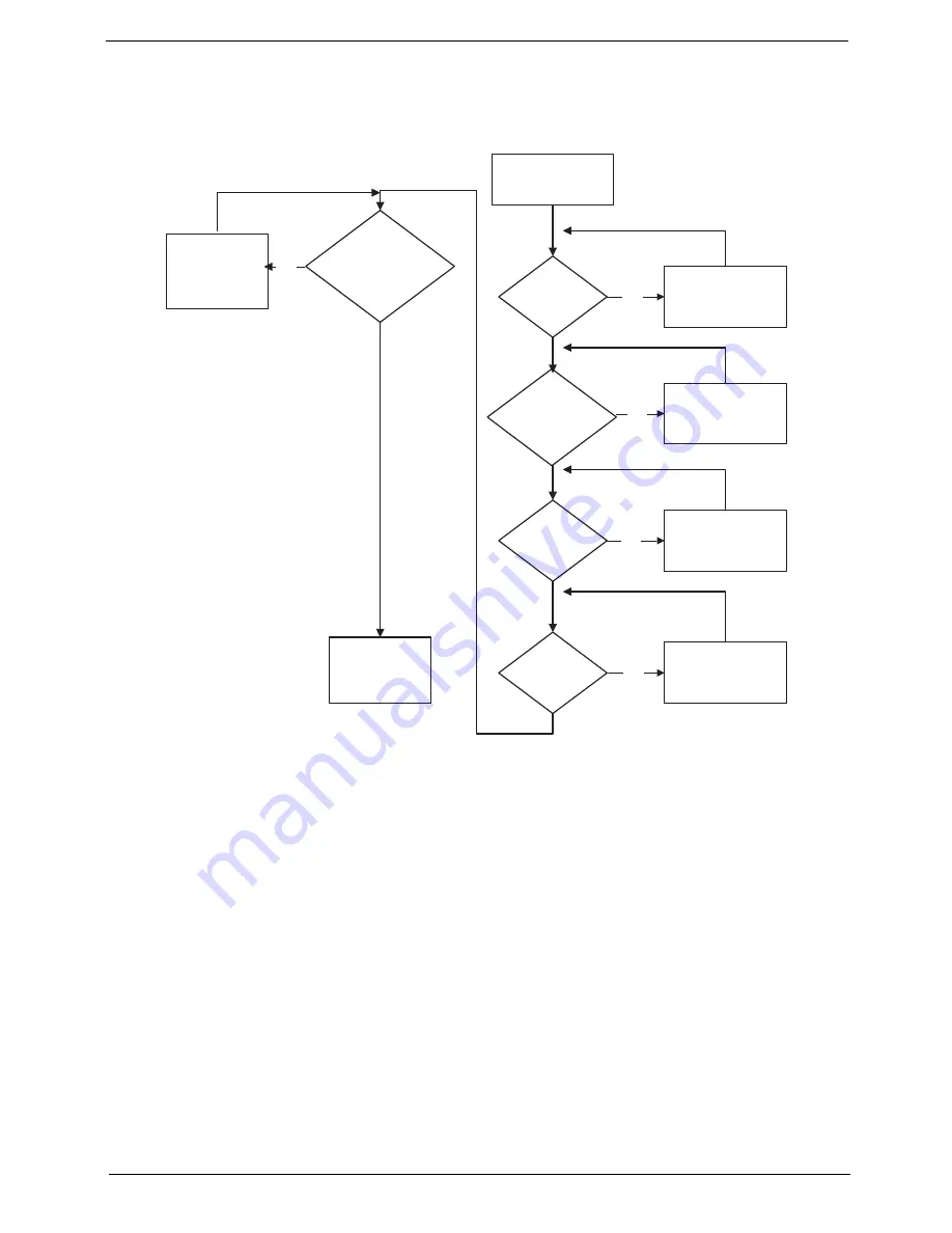
START
Power On ?
No
Go to No Power
troubleshooting
step
Replace external
DDRAM module
Remove and
replace thermal
module
Replace the
main board
Reconnect
SDRAM Module
LCD Module OK?
Replace LCD
Panel and
Cable
Ext. DDRAM module
connected properly?
Ext. DDRAM
module functional?
CPU Thermal
Module properly
connected?
No
No
No
No
Summary of Contents for AO752
Page 6: ...VI ...
Page 10: ...X Table of Contents ...
Page 34: ...24 Chapter 1 ...
Page 50: ...40 Chapter 2 ...
Page 59: ...Chapter 3 49 9 Detach the HDD board ...
Page 61: ...Chapter 3 51 5 Pull the memory module out 6 Repeat steps 4 and 5 for the second memory module ...
Page 73: ...Chapter 3 63 7 Unlock the touch pad FCC and pull the cable away ...
Page 87: ...Chapter 3 77 4 Pull the cables away from the two adhesive locations 5 Lift the modules away ...
Page 91: ...Chapter 3 81 5 Roll the bezel up and away from the hinges ...
Page 94: ...84 Chapter 3 4 Lift the LCD panel out lifting the bottom of the panel first ...
Page 106: ...96 Chapter 3 3 Apply adhesive and stick the microphone down ...
Page 117: ...Chapter 3 107 3 Connect the speaker connector ...
Page 135: ...Chapter 3 125 4 Tighten the four captive screws ...
Page 137: ...Chapter 3 127 4 Place the HDD cover in from one corner 5 Tighten the two captive screws ...
Page 140: ...130 Chapter 3 ...
Page 240: ...230 Appendix A ...
Page 250: ...240 Appendix B ...
Page 252: ...242 ...
Page 255: ...245 ...
Page 256: ...246 ...