


84
Chapter 3
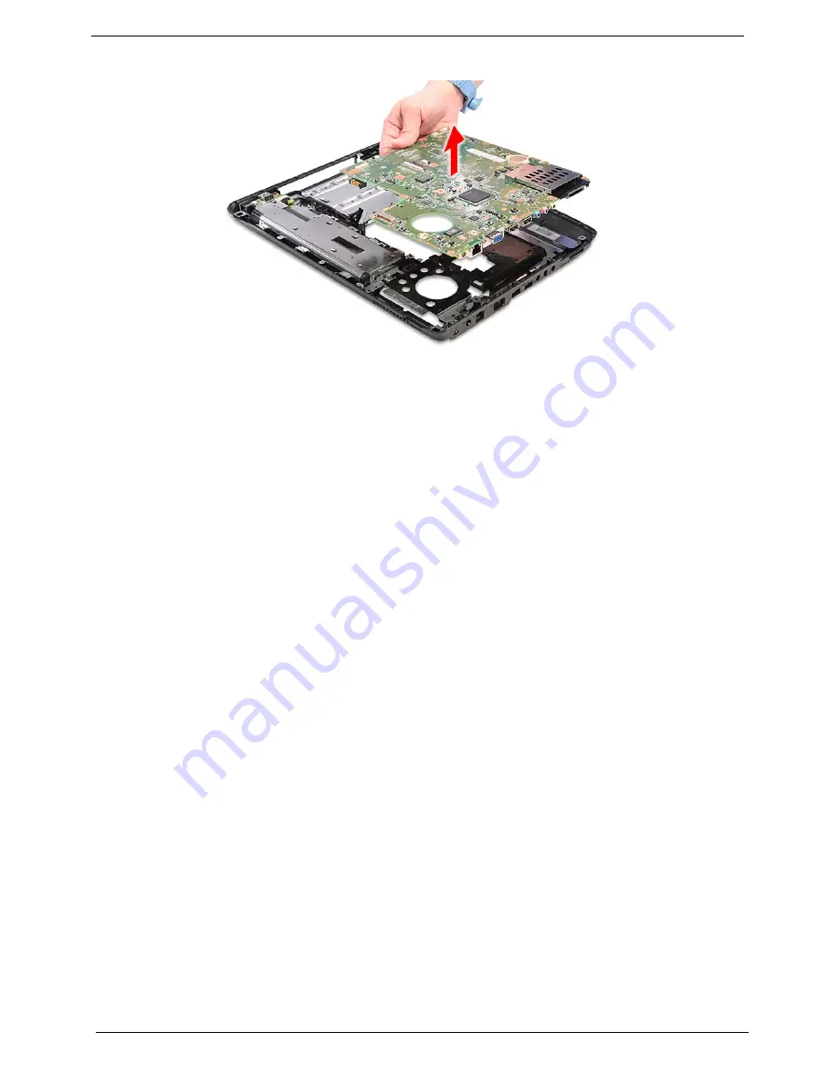
20.
Carefully remove the main board.
Removing the USB Board Module
1.
See “Removing the Battery Pack” on page 50.
2.
See “Removing the SD dummy card” on page 51.
3.
See “Removing the ExpressCard dummy card” on page 51.
4.
See “Removing the Lower Cover” on page 52.
5.
See “Removing the DIMM” on page 53.
6.
See “Removing the WLAN Board Modules” on page 54.
7.
See “Removing the Hard Disk Drive Module” on page 56.
8.
See “Removing the Optical Drive Module” on page 58.
9.
See “Removing the Middle Cover” on page 62.
10.
See “Removing the Keyboard” on page 63.
11.
See “Removing the Heatsink Fan Module” on page 64.
12.
See “Removing the CPU Heatsink Module” on page 65.
13.
See “Removing the CPU” on page 66.
14.
See “Removing the LCD Module” on page 67.
15.
See “Separating the Upper Case from the Lower Case” on page 70.
16.
See “Removing the Modem Board” on page 80.
Summary of Contents for 5335-2238 - Aspire - Celeron 2.16 GHz
Page 6: ...VI ...
Page 9: ...IX Table of Contents Online Support Information 159 Index 161 ...
Page 10: ...X Table of Contents ...
Page 56: ...46 Chapter 2 ...
Page 102: ...92 Chapter 3 13 Detach any adhesive tapes and any cable that is glued to the LCD panel ...
Page 106: ...96 Chapter 3 12 Remove the Web camera from the back cover ...
Page 120: ...110 Chapter 4 F5h Boot to Mini DOS F6h Clear Huge Segment F7h Boot to Full DOS Code Beeps ...
Page 127: ...Chapter 5 117 Top and Bottom View Jumper and Connector Locations Chapter 5 ...
Page 128: ...118 Chapter 5 ...
Page 132: ...122 Chapter 6 Aspire 5735 5735Z 5335 Series Exploded Diagram ...
Page 145: ...Chapter 6 135 ...
Page 146: ...Appendix A 136 Aspire 5735 5735Z 5335 Series Model Definition and Configuration Appendix A ...
Page 150: ...140 Appendix B ...
Page 152: ...142 Appendix C ...


