Acer 5335-2238 - Aspire - Celeron 2.16 GHz Service Manual Download Page 21

Chapter 1

11

Using the Keyboard

The keyboard has full-sized keys and an embedded numeric keypad, separate cursor, lock, Windows, function 
and special keys.

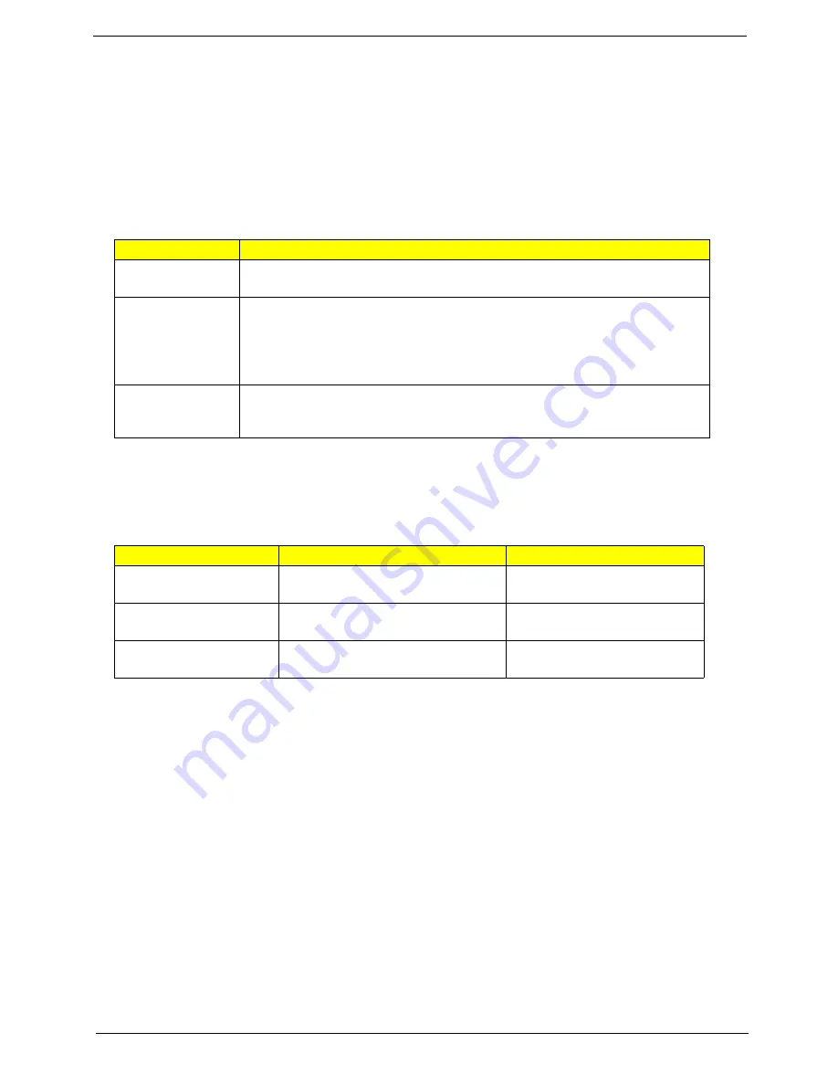
Lock Keys and embedded numeric keypad

The keyboard has three lock keys which you can toggle on and off.

The embedded numeric keypad functions like a desktop numeric keypad. It is indicated by small characters 
located on the upper right corner of the key caps. To simplify the keyboard legend, cursor-control key symbols 
are not printed on the keys.

Lock key

Description

Caps Lock

When Caps Lock is on, all alphabetic characters typed are 
in uppercase.

Num Lock 

<Fn> + <F11>

When Num Lock is on, the embedded keypad is in numeric mode. The keys 
function as a calculator (complete with the arithmetic ope, -, *, and /). 
Use this mode when you need to do a lot of numeric data entry. A better solution 
would be to connect an external keypad.

NOTE: 

<Fn> + <F11> works only for certain models.

Scroll Lock 

<Fn> + 

<F12>

When Scroll Lock is on, the screen moves one line up or down when you press 
the up or down arrow keys respectively. Scroll Lock does not work with some 
applications.

Desired access

Num Lock on

Num Lock off

Number keys on 
embedded keypad

Type numbers in a normal manner.

Cursor-control keys on 
embedded keypad

Hold 

<Shift> 

while using cursor-

control keys.

Hold 

<Fn>

 while using cursor-

control keys.

Main keyboard keys

Hold

 <Fn>

 while typing letters on 

embedded keypad.

Type the letters in a normal 
manner.

Summary of Contents for 5335-2238 - Aspire - Celeron 2.16 GHz

Page 1: ...Aspire 5735 5735Z 5335 Series Service Guide PRINTED IN TAIWAN Service guide files and updates are available on the ACER CSD web for more information please refer to http csd acer com tw ...

Page 2: ...II Revision History Please refer to the table below for the updates made on Aspire 5735 5735Z 5335 Series service guide Date Chapter Updates ...

Page 3: ...pect to the contents hereof and specifically disclaims any warranties of merchantability or fitness for any particular purpose Any Acer Incorporated software described in this manual is sold or licensed as is Should the programs prove defective following their purchase the buyer and not Acer Incorporated its distributor or its dealer assumes the entire cost of all necessary servicing repair and an...

Page 4: ... bits and pieces of additional information related to the current topic WARNING Alerts you to any damage that might result from doing or not doing specific actions CAUTION Gives precautionary measures to avoid possible hardware or software problems IMPORTANT Reminds you to do specific actions relevant to the accomplishment of procedures ...

Page 5: ... NOT be covered in this generic service guide In such cases please contact your regional offices or the responsible personnel channel to provide you with further technical details 2 Please note WHEN ORDERING FRU PARTS that you should check the most up to date information available on your regional web or channel If for whatever reason a part number change is made it will not be noted in the printe...

Page 6: ...VI ...

Page 7: ... 23 Using the System Utilities 24 Acer GridVista dual display compatible 24 Hardware Specifications and Configurations 26 System Utilities 33 BIOS Setup Utility 33 Navigating the BIOS Utility 34 Information 35 Main 36 Security 38 Boot 42 Exit 43 BIOS Flash Utility 44 Remove HDD BIOS Utility 45 Machine Disassembly and Replacement 47 Disassembly Requirements 47 General Information 48 Pre disassembly...

Page 8: ...kets 93 Removing the Antennas 94 Removing the Web Camera 95 Troubleshooting 97 System Check Procedures 98 External Diskette Drive Check 98 External CD ROM Drive Check 98 Keyboard or Auxiliary Input Device Check 98 Memory Check 99 Power System Check 99 Touchpad Check 101 Power On Self Test POST Error Message 102 Index of Error Messages 103 Phoenix BIOS Beep Codes 106 Index of Symptom to FRU Error M...

Page 9: ...IX Table of Contents Online Support Information 159 Index 161 ...

Page 10: ...X Table of Contents ...

Page 11: ...T3200 T3400 for Aspire 5735Z Intel Celeron M 575 585 T1600 for Aspire 5335 System Memory Dual channel SDRAM support Up to 1 GB of DDR2 667 MHz memory upgradeable to 2 GB using two soDIMM modules Up to 2 GB of DDR2 667 MHz memory upgradeable to 4 GB using two soDIMM modules Display and graphics 15 6 HD 1366 x 768 Mobile Intel GL40 GM45 Express Chipset GM45 for Aspire 5735 5735Z 5335 Storage subsyst...

Page 12: ...s ExpressCard 54 slot 5 in 1 card reader SD MMC MS MS PRO xD Three USB 2 0 ports External display VGA port Headphones speaker line out jack Microphone in jack Line in jack Ethernet RJ 45 port Modem RJ 11 port DC in jack for AC adapter Environment Temperature Operating 5 C to 35 C Non operating 20 C to 65 C Humidity non condensing Operating 20 to 80 Non operating 20 to 80 NOTE Only for certain mode...

Page 13: ...65 A03 THERMAL EMC2102 Codec ALC268 MIC In MDC Card APA2057 OP AMP AZALIA MODEM INT SPKR Line Out NO SPDIF RJ11 AGTL CPU I F DDR Memory I F INTEGRATED GRAHPICS LVDS CRT I F 6 PCIe ports PCI PCI BRIDGE ACPI 2 0 4 SATA 12 USB 2 0 1 1 ports 667 800 MHz CardReader Realtek RTS5158E USB ETHERNET 10 100 1000MbE High Definition Audio LPC I F Serial Peripheral I F Matrix Storage Technology DO Active Manage...

Page 14: ... 2 Display screen Also called Liquid Crystal Display LCD displays computer output 3 Power button Turns the computer on and off 4 Empowering key Launch Acer Empowering Technology 5 Keyboard For entering data into your computer 6 Touchpad Touch sensitive pointing device which functions like a computer mouse 7 14 Status indicators Light Emitting Diodes LEDs that light up to show the status of the com...

Page 15: ...nds when you use the computer 10 Speakers Left and right speakers deliver stereo audio output 11 Microphone Internal microphone for sound recording 12 Easy launch buttons Buttons for launching frequently used programs 13 VOL VOL Volume up Volume down Increases the sound volume Decreases the sound volume Icon Item Description 1 Latch Locks and releases the lid Icon Item Description ...

Page 16: ...t from external microphones 5 Headphones speaker line out jack with S PDIF support Connects to audio line out devices e g speakers headphones 6 5 in 1 card reader Accepts Secure Digital SD MultiMediaCard MMC Memory Stick MS Memory Stick PRO MS PRO xD Picture Card xD 7 ExpressCard 54 slot Accepts one ExpressCard 54 module Icon Item Description 1 Optical drive Internal optical drive accepts CDs or D...

Page 17: ...ect hole to eject the optical drive tray when the computer is off 5 Modem RJ 11 port Connects to a phone line 6 DC in jack Connects to an AC adapter 7 Kensington lock slot Connects to a Kensington compatible computer security lock Icon Item Description 1 Ventilation slots Enable the computer to stay cool even after prolonged use Icon Item Description ...

Page 18: ...battery for removal 3 Battery lock Locks the battery in position 4 Memory compartment Houses the computer s main memory 5 Hard disk bay Houses the computer s hard disk secured with screws 6 Ventilation slots and cooling fan Enable the computer to stay cool even after prolonged use Note Do not cover or obstruct the opening of the fan ...

Page 19: ...an access the Launch Manager by clicking on Start All Programs and then Launch Manager to start the application Icon Function Description HDD Indicates when the hard disk drive is active Num Lock Lights up when Num Lock is activated Caps Lock Lights up when Caps Lock is activated Power Indicates the computer s power status Battery Indicates the computer s battery status Icon Function Description W...

Page 20: ...uchpad keep it and your fingers dry and clean The touchpad is sensitive to finger movement hence the lighter the touch the better the response Tapping harder will not increase the touchpad s responsiveness NOTE By default vertical and horizontal scrolling is enabled on your touchpad It can be disabled under Mouse settings in Windows Control Panel Function Left button 2 Right button 3 Main touchpad...

Page 21: ...F11 When Num Lock is on the embedded keypad is in numeric mode The keys function as a calculator complete with the arithmetic operators and Use this mode when you need to do a lot of numeric data entry A better solution would be to connect an external keypad NOTE Fn F11 works only for certain models Scroll Lock Fn F12 When Scroll Lock is on the screen moves one line up or down when you press the u...

Page 22: ...rk domain M Minimizes all windows R Open the Run dialog box T Cycle through programs on the taskbar U Open Ease of Access Center X Open Windows Mobility Center BREAK Display the System Properties dialog box SHIFT M Restore minimized windows to the desktop TAB Cycle through programs on the taskbar by using Windows Flip 3 D SPACEBAR Bring all gadgets to the front and select Windows Sidebar CTRL F Se...

Page 23: ... Launches Acer ePower Management in Acer Empowering Technology Fn F4 Sleep Puts the computer in Sleep mode Fn F5 Display toggle Switches display output between the display screen external monitor if connected and both Fn F6 Screen blank Turns the display screen backlight off to save power Press any key to return Fn F7 Touchpad toggle Turns the internal touchpad on and off Fn F8 Speaker toggle Turn...

Page 24: ...ard or hold Alt Gr and then press the 5 key at the upper center of the keyboard NOTE Some fonts and software do not support the Euro symbol Please refer to www microsoft com typography faq faq12 htm for more information The US dollar sign 1 Open a text editor or word processor 2 Either press at the bottom right of the keyboard or hold Shift and then press the 4 key at the upper center of the keybo...

Page 25: ...articular utility launch the utility and click the icon at the bottom of the active window Launching Acer Empowering Technology To launch Acer Empowering Technology 1 Press the Empowering Key to display the Acer Empowering Technology toolbar on the desktop 2 To hide the toolbar press the Empowering Key again or click the hide button on the toolbar You may also launch Acer Empowering Technology by ...

Page 26: ...he Restore tab 3 Click Password settings The Empowering Technology Password Center dialogue box pops up 4 Click Create a new password 5 In the Create a New Password dialogue box key in and confirm your password in the appropriate boxes Your password should have a minimum of 4 and a maximum of 12 characters 6 Enter a password hint that will help you remember your password 7 Make sure the box Use fo...

Page 27: ...Theater on your system Select Movie or Game mode to experience the awesome realism of 5 1 channel audio output from the speakers fitted to your system via Dolby Surround sound technology Music mode lets you enjoy your favorite tunes in vivid detail To choose your playback device click the icon on the upper right side of the Acer eAudio Management window ...

Page 28: ...ined power plan to base your customized plan on 4 If necessary change the display sleep and hibernation settings you want your computer to use 5 Click OK to save your new power plan To switch between power plans 1 Move your mouse over the Acer ePower Management application on the Acer Empowering Technology toolbar The quick menu appears Select the power plan you want to switch to 2 You may also sw...

Page 29: ...ment only for certain models Acer eDataSecurity Management is an encryption utility that protects your files from being accessed by unauthorized persons It is conveniently integrated with Windows Explorer as a shell extension for quick data encryption decryption and also supports on the fly file encryption for Lotus Notes and Microsoft Outlook On first use the Acer eDataSecurity Management setup w...

Page 30: ...able of decrypting the file If you lose both passwords there will be no way to decrypt your encrypted file Be sure to safeguard all related passwords Acer eRecovery Management Acer eRecovery Management is a versatile backup utility It allows you to create full or incremental backups burn the factory default image to optical disc and restore from previously created backups or reinstall applications...

Page 31: ...echnology password To set the password refer to the section Empowering Technology password For more information please refer to Acer eRecovery Management on page 62 in the Acer System User s Guide NOTE If your computer did not come with a Recovery CD or System CD please use Acer eRecovery Management s Backup factory default to CD DVD feature to burn a backup image to CD or DVD To ensure the best r...

Page 32: ...nt allows you to inspect hardware specifications set BIOS passwords and modify boot options Acer eSettings Management also Provides a simple graphical user interface for navigation Prints and saves hardware specifications Lets you set an asset tag for your system ...

Page 33: ...chronization status and presentation settings Windows Mobility Center also includes Acer specific settings like sharing folders overview sharing service on or off Bluetooth Add Device if applicable and a shortcut to the Acer user guide drivers and utilities To launch Windows Mobility Center q Use the shortcut key X q Start Windows Mobility Center from the Control panel q Start Windows Mobility Cen...

Page 34: ...offers four pre defined display settings so you can view multiple windows on the same screen To access this function please go to Start All Programs and click on Acer GridVista You may choose any one of the four display settings indicated below Double vertical Triple primary at left Triple primary at right or Quad Acer Gridvista is dual display compatible allowing two displays to be partitioned in...

Page 35: ...Chapter 1 25 NOTE Please ensure that the resolution setting of the second monitor is set to the manufacturer s recommended value ...

Page 36: ... voltage 1 0375V to 1 3V CPU Fan True Value Table DTS degree C Fan Speed rpm Acoustic Level dBA 45 50 0 3000 29 55 66 0 3300 33 68 74 3300 3800 38 78 83 3800 4100 40 86 91 4100 4800 40 BIOS Item Specification BIOS vendor Phoenix BIOS Version 1 04c System Memory Item Specification Memory controller Built in Memory size 0MB no on board memory DIMM socket number 2 sockets Supports memory size per soc...

Page 37: ...8MB 2048MB 4096MB Item Specification LAN Chipset Marvell 88E8071 Supports LAN protocol 10 100 1000 Mbps LAN connector type RJ45 LAN connector location Left side Features Integrated 10 100 BASE T transceiver Wake on LAN support compliant with ACPI 2 0 PCI v2 2 Bluetooth Interface Item Specification Chipset Foxconn Bluetooth FOX_BRM_2 0 F W 300 built in ICH9M on the main board Data throughput 723 bp...

Page 38: ...rive Format Disks 2 2 2 N A Spindle speed RPM 5400 RPM 5400 RPM 5400 RPM 5400 RPM Performance Specifications Buffer size 8MB 8MB 8MB 8MB Interface SATA SATA SATA SATA Max media transfer rate disk buffer Mbytes s 540 540 540 850 DC Power Requirements Voltage tolerance 5V DC 5 5V DC 5 5V DC 5 5V DC 5 Optical Disc Drive Item Specification Vendor model name TOSHIBA SUPER MULTI DRIVE DL 8X TS L633A LF ...

Page 39: ... Part CD RW HSRW Orange Book Part Volume1 Volume 2 Super Audio CD SACD Hybrid type US US RW DVD DVD ROM Book 1 02 DVD Dual DVD Video Book 1 1 DVD R Book 1 0 3 9G DVD R Book 2 0 4 7G General Authoring DVD R Version 1 0 DVD RW DVD RW Non CPRM CPRM DVD R Dual Loading mechanism Load Manual Release a Electrical Release Release Button b Release by ATAPI command c Emergency Release Power Requirement Inpu...

Page 40: ...ic Mobile Intel GL45 ICH9M Express Chipset VGA GL45 USB 2 0 Intel ICH9M Super I O controller N A MODEM ALC 268 Bluetooth FOXCONN BCM2045 V2 built in ICH9M on the main board Wireless 802 11 b g WLAN 802 11ABGN SHIRLEYPEAK1 2 built in ICH9M on the main board PCMCIA 5 in 1 Card Reader Realtec RTS5158E Audio Codec Audio Azalia ALC268 Keyboard Item Specification Keyboard controller ENE 3310 Total numbe...

Page 41: ...tness 220 Luminance Uniformity 1 25 max Contrast Ratio 400 typical Response Time msec 8 Nominal Input Voltage VDD 3 3V Viewing Angle degree Horizontal Right Left Vertical Upper Lower 45 45 15 35 Temperature Range C Operating Storage shipping 0 to 50 40 to 60 AC Adaptor Item Specification Input 100 240V 1 5A 50 60Hz Output 19V 4 74A 90W 19V 3 42A 65W System Power Management ACPI mode Power Manageme...

Page 42: ...spend Audio Power Down Hard Disk Power Down CD ROM Power Down Super I O Low Power mode Save to Disk S4 Also called Hibernation Mode System saves all system states and data onto the disc prior to power off the whole system System Power Management ACPI mode Power Management ...

Page 43: ...ce without entering BIOS Setup Utility please set the parameter to enabled Press F12 during POST to enter multi boot menu In this menu user can change boot device without entering BIOS SETUP Utility Phoenix SecureCore tm Setup Utility Main CPU Type CPU Speed IDE0 Model Name IDE0 Serial Number ATAPI Model Name System BIOS Version VGA BIOS Version KBC Version Serial Number Asset Tag Number Product N...

Page 44: ... Press Esc while you are in any of the menu options to go to the Exit menu q In any menu you can load default settings by pressing F9 You can also press F10 to save any changes made and exit the BIOS Setup Utility NOTE You can change the value of a parameter if it is enclosed in square brackets Navigation keys for a particular menu are shown on the bottom of the screen Help for parameters are foun...

Page 45: ...Asset Tag Number This field displays the asset tag number of the system Product Name This field shows product name of the system Manufacturer Name This field displays the manufacturer of this system UUID Number Universally Unique Identifier UUID is an identifier standard used in software construction standardized by the Open Software Foundation OSF as part of the Distributed Computing Environment ...

Page 46: ...e tm Setup Utility Main Item Specific Help Tab Shift Tab or Enter selects field System Time System Date System Memory Extended Memory Video Memory Quiet Boot Network Boot F12 Boot Menu D2D Recovery SATAMode F1 Esc Help Exit Select Item Select Menu Change Values Select Sub Menu Enter F9 F10 Setup Defaults Save and Exit Information Security Boot Exit 10 10 07 26 2008 640 KB 4061 MB 32 MB Enabled Ena...

Page 47: ... memory size of the extended memory in the system Extended Memory size Total memory size 1MB VGA Memory Shows the VGA memory size Quiet Boot Determines if Customer Logo will be displayed or not shows Summary Screen is disabled or enabled Enabled Customer Logo is displayed and Summary Screen is disabled Disabled Customer Logo is not displayed and Summary Screen is enabled Option Enabled or Disabled...

Page 48: ...ty Main F1 Esc Help Exit Select Item Select Menu Change Values Select Sub Menu Enter F9 F10 Setup Defaults Save and Exit Information Security Boot Exit Item Specific Help Supervisor Password controls access of the whole setup utility It can be used to boot up when Password on boot is enabled Supervisor Password s User Password s Set User Password Set Password Password on Boot i i HDD Password is H...

Page 49: ...ired you can opt to enable the Password on boot parameter 5 When you are done press u to save the changes and exit the BIOS Setup Utility Parameter Description Option Supervisor Password Is Shows the setting of the Supervisor password Clear or Set User Password Is Shows the setting of the user password Clear or Set HDD Password Is Shows the setting of the hard disk password Clear or Set Set Superv...

Page 50: ...e BIOS Setup Utility Changing a Password 1 Use the w and y keys to highlight the Set Supervisor Password parameter and press the e key The Set Password box appears 2 Type the current password in the Enter Current Password field and press e 3 Type a password in the Enter New Password field Retype the password in the Confirm New Password field 4 Press e After setting the password the computer sets t...

Page 51: ...current password entered does not match the actual current password the screen will show you the Setup Warning If the new password and confirm new password strings do not match the screen will display the following message ...

Page 52: ...etup Utility Main Item Specific Help Use or to select a device then press F6 to move it up the list or F5 to move it down the list Press Esc to escape the menu Boot priority order F1 Esc Help Exit Select Item Select Menu Change Values Select Sub Menu Enter F9 F10 Setup Defaults Save and Exit Information Security Boot Exit 2 3 4 5 6 7 XXXXXXXXXXX XXX XX XXXX XX PCI LAN Network Boot USB HDD USB FDD ...

Page 53: ... saving setup data to CMOS Load Setup Default Load default values for all SETUP item Discard Changes Load previous values from CMOS for all SETUP items Save Changes Save Setup Data to CMOS Phoenix SecureCore tm Setup Utility Main Item Specific Help Exit System Setup and save your changes to CMOS F1 Esc Help Exit Select Item Select Menu Change Values Select Sub Menu Enter F9 F10 Setup Defaults Save...

Page 54: ...very Diskette before you use the Flash utility NOTE Do not install memory related drivers XMS EMS DPMI when you use the Flash NOTE Please use the AC adaptor power supply when you run the Flash utility If the battery pack does not contain enough power to finish BIOS flash you may not boot the system because the BIOS is not completely loaded Fellow the steps below to run the Flash 1 Prepare a bootab...

Page 55: ...u key in wrong HDD password for three time HDD password error code would display on the screen See the image below q If you need to solve HDD password locked problem you can run HDD_PW EXE 1 Key in hdd_pw 15494 0 2 Select 2 3 Choose one upper case string q Reboot system and key in 0KJFN42 or UVEIQ96 to HDD user password ...

Page 56: ...46 Chapter 2 ...

Page 57: ...tools Wrist grounding strap and conductive mat for preventing electrostatic discharge Flat screwdriver Philips screwdriver Hex screwdriver Plastic flat screwdriver Plastic tweezers NOTE The screws for the different components vary in size During the disassembly process group the screws with the corresponding components to avoid mismatch when putting back the components Chapter 3 Machine Disassembl...

Page 58: ...ain unit disassembly LCD module disassembly The flowcharts provided in the succeeding disassembly sections illustrate the entire disassembly sequence Observe the order of the sequence to avoid damage to any of the hardware components For example if you want to remove the main board you must first remove the keyboard then disassemble the inside assembly frame in that order Main Screw List Item Scre...

Page 59: ...he keyboard then disassemble the inside assembly frame in that order Screw List Item Screw Color Part No A M2 x L8 Black 86 00E34 738 C M2 x L3 Silver 86 9A522 3R0 D M3 x L4 Silver 86 9A524 4R0 H M2 x L3 Black 86 9A552 3R0 EXTERNAL MODULE DISASSEMBLY WLAN BOARD TURN OFF POWER AND PERIPHERALS UNPLUG POWER CABLES Hx1 LOWER COVER Captive Screwx4 DIMM MODULES Dx2 HDD MODULE HARD DISK BRACKET HARD DISK...

Page 60: ...attery Pack 1 Turn base unit over 2 Slide the battery lock unlock latch to the unlock position 3 Slide the battery release latch to the release position to pop out the battery pack then remove the battery pack from the main unit ...

Page 61: ... 3 51 Removing the SD dummy card 1 Push the SD dummy card all the way in to eject it 2 Pull it out from the slot Removing the ExpressCard dummy card 1 Push the ExpressCard dummy card all the way in to eject it ...

Page 62: ... out from the slot Removing the Lower Cover 1 See Removing the Battery Pack on page 50 2 Remove the four captive screws and the six screws A on the lower cover Step Size Quantity Color Torque 1 6 M2 5 x L8 6 Black 3 0 kgf cm ...

Page 63: ...lly pry open the lower cover 4 Remove the lower cover from the lower case Removing the DIMM 1 See Removing the Battery Pack on page 50 2 See Removing the Lower Cover on page 52 3 Push out the latches on both sides of the DIMM socket to release the DIMM ...

Page 64: ... 4 Remove the DIMM module Removing the WLAN Board Modules 1 See Removing the Battery Pack on page 50 2 See Removing the Lower Cover on page 52 3 Remove the white antenna cable that is taped to the WLAN board module ...

Page 65: ... WLAN board module The Black antenna cable is connected to the MAIN connector and the Gray antenna cable is connected to the AUX connector 5 Move the antenna away from the WLAN board and remove the one screw H on the WLAN board to release the WLAN board Step Size Quantity Color Torque 1 M2 x L3 1 Black 1 6 kgf cm ...

Page 66: ...the WLAN board make sure the cable are arranged properly Removing the Hard Disk Drive Module 1 See Removing the Battery Pack on page 50 2 See Removing the Lower Cover on page 52 3 Remove the one screw C securing the hard disk drive module Step Size Quantity Color Torque 1 M2 x L3 1 Silver 1 6 kgf cm ...

Page 67: ...way from the connector 5 Lift the hard disk drive module and remove it from the hard disk drive bay NOTE To prevent damage to device avoid pressing down on it or placing heavy objects on top of it 6 Remove the two adhesive tape covering the two screws ...

Page 68: ...e hard disk to the bracket and remove the hard disk from the bracket Removing the Optical Drive Module 1 See Removing the Battery Pack on page 50 2 See Removing the Lower Cover on page 52 Step Size Quantity Color Torque 1 2 M3 x L4 2 Silver 3 0 kgf cm ...

Page 69: ...ole to eject the odd drive tray 4 Carefully pull out the odd drive tray until the part of the module is visible and then slowly push back to close the tray into the module with the module still partially exposed 5 Slowly pull out the odd module from the odd drive bay ...

Page 70: ...60 Chapter 3 6 Remove the two screws C securing the locker bracket and remove the locker bracket from the optical disk drive module Step Size Quantity Color Torque 1 2 M2 x L3 2 Silver 1 6 kgf cm ...

Page 71: ... 5 x L10 Silver 86 00F84 73A G M2 x L4 Black 86 00A02 140 H M2 x L3 Black 86 9A552 3R0 MAIN UNIT KEYBOARD MAIN BOARD Cx1 MAIN UNIT DISASSEMBLY LCD MODULE C x 1 Ax2 Ex2 UPPER CASE A x 11 G x 4 CPU THERMAL MODULE CPU SCREW X 4 Cx1 BLUETOOTH MODULE HEAT SINK FAN TOUCHPAD BRACKET MIDDLE COVER LED BOARD SPEAKER MODULE C x 4 C x 2 TOUCHPAD MODULE USB MODULE MODEM CARD C x 1 C x 1 ...

Page 72: ...he Middle Cover 1 See Removing the Battery Pack on page 50 2 Use a plastic screw driver to pry loose the side of the middle cover 3 Carefully pry loose the middle cover from the latches securing it and remove the middle cover ...

Page 73: ... Removing the Battery Pack on page 50 2 See Removing the Middle Cover on page 62 3 Push down on the lock and release the latches securing the keyboard to the upper case 4 Carefully pry loose the keyboard and turn it over on the touchpad area ...

Page 74: ...yboard cable from the main board to remove the keyboard Removing the Heatsink Fan Module 1 See Removing the Battery Pack on page 50 2 See Removing the Lower Cover on page 52 3 Disconnect the heatsink fan connector from the main board ...

Page 75: ...ace 5 Carefully lift up the heatsink fan module Removing the CPU Heatsink Module 1 See Removing the Battery Pack on page 50 2 See Removing the Lower Cover on page 52 3 See Removing the Heatsink Fan Module on page 64 Step Size Quantity Color Torque 1 M2 x L3 1 Silver 1 6 kgf cm ...

Page 76: ...e from the system Removing the CPU 1 See Removing the Battery Pack on page 50 2 See Removing the Lower Cover on page 52 3 See Removing the Heatsink Fan Module on page 64 4 See Removing the CPU Heatsink Module on page 65 5 Using a flat screwdriver turn the CPU socket latch counter clockwise to release the CPU ...

Page 77: ...See Removing the Battery Pack on page 50 2 See Removing the SD dummy card on page 51 3 See Removing the ExpressCard dummy card on page 51 4 See Removing the Lower Cover on page 52 5 See Removing the WLAN Board Modules on page 54 6 See Removing the Middle Cover on page 62 7 See Removing the Heatsink Fan Module on page 64 8 See Removing the CPU Heatsink Module on page 65 ...

Page 78: ...Turn over the system and remove the two screws A from the bottom of the left and right hinges 10 Disconnect the LCD cable connector from the main board Step Size Quantity Color Torque 1 2 M2 5 x L8 2 Black 3 0 kgf cm ...

Page 79: ...ll out the wireless antenna cables from the hole and release the cables from the latches 12 Remove the two screws E from the left and right hinge of the LCD module Step Size Quantity Color Torque 1 2 M2 5 x L10 2 Silver 3 0 kgf cm ...

Page 80: ...essCard dummy card on page 51 4 See Removing the Lower Cover on page 52 5 See Removing the DIMM on page 53 6 See Removing the WLAN Board Modules on page 54 7 See Removing the Hard Disk Drive Module on page 56 8 See Removing the Optical Drive Module on page 58 9 See Removing the Middle Cover on page 62 10 See Removing the Keyboard on page 63 11 See Removing the Heatsink Fan Module on page 64 12 See...

Page 81: ...Chapter 3 71 15 Disconnect the touchpad cable from the TPAD1 connector on the main board 16 Disconnect the LED cable from LEDCN1 on the main board ...

Page 82: ...ct the speaker cable from the INTSPK1 connector on the main board 18 Remove the eleven screws 11 x A 1 x G from the bottom panel Step Size Quantity Color Torque 1 11 M2 5 x L8 11 Black 3 0 kgf cm 12 M2 x L4 1 Black 3 0 kgf cm ...

Page 83: ...n page 51 3 See Removing the ExpressCard dummy card on page 51 4 See Removing the Lower Cover on page 52 5 See Removing the DIMM on page 53 6 See Removing the WLAN Board Modules on page 54 7 See Removing the Hard Disk Drive Module on page 56 8 See Removing the Optical Drive Module on page 58 9 See Removing the Middle Cover on page 62 10 See Removing the Keyboard on page 63 Step Size Quantity Color...

Page 84: ...nk Module on page 65 13 See Removing the CPU on page 66 14 See Removing the LCD Module on page 67 15 See Separating the Upper Case from the Lower Case on page 70 16 Disconnect the LED cable from the LED board 17 Disconnect the internal microphone cable from the INTMIC1 connector on the LED board ...

Page 85: ...See Removing the ExpressCard dummy card on page 51 4 See Removing the Lower Cover on page 52 5 See Removing the DIMM on page 53 6 See Removing the WLAN Board Modules on page 54 7 See Removing the Hard Disk Drive Module on page 56 8 See Removing the Optical Drive Module on page 58 9 See Removing the Middle Cover on page 62 10 See Removing the Keyboard on page 63 Step Size Quantity Color Torque 1 M2...

Page 86: ...e 65 13 See Removing the CPU on page 66 14 See Removing the LCD Module on page 67 15 See Separating the Upper Case from the Lower Case on page 70 16 Remove the four screws C securing the speaker module 17 Remove the tape covering the speaker cable Step Size Quantity Color Torque 1 4 M2 x L3 4 Silver 1 6 kgf cm ...

Page 87: ...pressCard dummy card on page 51 4 See Removing the Lower Cover on page 52 5 See Removing the DIMM on page 53 6 See Removing the WLAN Board Modules on page 54 7 See Removing the Hard Disk Drive Module on page 56 8 See Removing the Optical Drive Module on page 58 9 See Removing the Middle Cover on page 62 10 See Removing the Keyboard on page 63 11 See Removing the Heatsink Fan Module on page 64 12 S...

Page 88: ...CPU on page 66 14 See Removing the LCD Module on page 67 15 See Separating the Upper Case from the Lower Case on page 70 16 Remove the touchpad cable that is glued to the bracket 17 Disconnect the touchpad cable from the touchpad board ...

Page 89: ...Chapter 3 79 18 Remove the two screws C securing the bracket to the upper case 19 Remove the touchpad bracket Step Size Quantity Color Torque 1 2 M2 x L2 2 Silver 1 6 kgf cm ...

Page 90: ... page 51 3 See Removing the ExpressCard dummy card on page 51 4 See Removing the Lower Cover on page 52 5 See Removing the DIMM on page 53 6 See Removing the WLAN Board Modules on page 54 7 See Removing the Hard Disk Drive Module on page 56 8 See Removing the Optical Drive Module on page 58 9 See Removing the Middle Cover on page 62 10 See Removing the Keyboard on page 63 11 See Removing the Heats...

Page 91: ... Removing the LCD Module on page 67 15 See Separating the Upper Case from the Lower Case on page 70 16 Remove the one screw C securing the modem card 17 Lift the modem board from the main board Step Size Quantity Color Torque 1 M2 x L3 1 Silver 1 6 kgf cm ...

Page 92: ...ving the WLAN Board Modules on page 54 7 See Removing the Hard Disk Drive Module on page 56 8 See Removing the Optical Drive Module on page 58 9 See Removing the Middle Cover on page 62 10 See Removing the Keyboard on page 63 11 See Removing the Heatsink Fan Module on page 64 12 See Removing the CPU Heatsink Module on page 65 13 See Removing the CPU on page 66 14 See Removing the LCD Module on pag...

Page 93: ... from the USBCN1 connector on the main board 18 Disconnect the bluetooth cable from the BLUE1 connector on the main board 19 Remove the one screw C securing the main board in place Step Size Quantity Color Torque 1 M2 x L3 1 Silver 1 6 kgf cm ...

Page 94: ...ng the WLAN Board Modules on page 54 7 See Removing the Hard Disk Drive Module on page 56 8 See Removing the Optical Drive Module on page 58 9 See Removing the Middle Cover on page 62 10 See Removing the Keyboard on page 63 11 See Removing the Heatsink Fan Module on page 64 12 See Removing the CPU Heatsink Module on page 65 13 See Removing the CPU on page 66 14 See Removing the LCD Module on page ...

Page 95: ...ove the one screw C securing the USB board module to the lower case 18 Release the USB cable from the latch 19 Remove the USB board module from the lower case Step Size Quantity Color Torque 1 M2 x L3 1 Silver 1 6 kgf cm ...

Page 96: ...Drive Module on page 56 8 See Removing the Optical Drive Module on page 58 9 See Removing the Middle Cover on page 62 10 See Removing the Keyboard on page 63 11 See Removing the Heatsink Fan Module on page 64 12 See Removing the CPU Heatsink Module on page 65 13 See Removing the CPU on page 66 14 See Removing the LCD Module on page 67 15 See Separating the Upper Case from the Lower Case on page 70...

Page 97: ...ly Flowchart Screw List Item Screw Color Part No B M2 5 x L6 Black 86 00E12 536 F M2 x L4 Silver 86 00C07 220 LCD MODULE LCD BEZEL Bx4 LCD ASSEMBLY LEFT LCD BRACKET Fx2 RIGHT LCD BRACKET Fx2 LCD FPC CABLE LCD BACK PANEL ANTENNAS LCD MODULE DISASSEMBLY Bx5 VGA CAMERA ...

Page 98: ...page 52 5 See Removing the WLAN Board Modules on page 54 6 See Removing the Middle Cover on page 62 7 See Removing the Heatsink Fan Module on page 64 8 See Removing the CPU Heatsink Module on page 65 9 See Removing the LCD Module on page 67 10 Remove the four screw covers from the LCD bezel 11 Remove the four screws B on the LCD module as shown Step Size Quantity Color Torque 1 4 M2 5 x L6 4 Black...

Page 99: ...e SD dummy card on page 51 3 See Removing the ExpressCard dummy card on page 51 4 See Removing the Lower Cover on page 52 5 See Removing the WLAN Board Modules on page 54 6 See Removing the Middle Cover on page 62 7 See Removing the Heatsink Fan Module on page 64 8 See Removing the CPU Heatsink Module on page 65 9 See Removing the LCD Module on page 67 10 See Removing the LCD Bezel on page 88 ...

Page 100: ...2 Remove the five screws 5 x B securing the LCD module 13 Remove the LCD with the brackets from the back cover Removing the Inverter Board and FPC Cable 1 See Removing the Battery Pack on page 50 Step Size Quantity Color Torque 1 5 M2 5 x L6 5 Black 3 0 kgf cm ...

Page 101: ... the WLAN Board Modules on page 54 6 See Removing the Middle Cover on page 62 7 See Removing the Heatsink Fan Module on page 64 8 See Removing the CPU Heatsink Module on page 65 9 See Removing the LCD Module on page 67 10 See Removing the LCD Bezel on page 88 11 See Removing the LCD panel with the Brackets on page 89 12 Disconnect the cables from the inverter board ...

Page 102: ...92 Chapter 3 13 Detach any adhesive tapes and any cable that is glued to the LCD panel ...

Page 103: ...oving the WLAN Board Modules on page 54 6 See Removing the Middle Cover on page 62 7 See Removing the Heatsink Fan Module on page 64 8 See Removing the CPU Heatsink Module on page 65 9 See Removing the LCD Module on page 67 10 See Removing the LCD Bezel on page 88 11 See Removing the LCD panel with the Brackets on page 89 12 See Removing the Inverter Board and FPC Cable on page 90 13 Remove the fo...

Page 104: ...he WLAN Board Modules on page 54 6 See Removing the Middle Cover on page 62 7 See Removing the Heatsink Fan Module on page 64 8 See Removing the CPU Heatsink Module on page 65 9 See Removing the LCD Module on page 67 10 See Removing the LCD Bezel on page 88 11 See Removing the LCD panel with the Brackets on page 89 12 Release the antenna cables from the aluminium tapes Step Size Quantity Color Tor...

Page 105: ...oving the SD dummy card on page 51 3 See Removing the ExpressCard dummy card on page 51 4 See Removing the Lower Cover on page 52 5 See Removing the WLAN Board Modules on page 54 6 See Removing the Middle Cover on page 62 7 See Removing the Heatsink Fan Module on page 64 8 See Removing the CPU Heatsink Module on page 65 9 See Removing the LCD Module on page 67 10 See Removing the LCD Bezel on page...

Page 106: ...96 Chapter 3 12 Remove the Web camera from the back cover ...

Page 107: ...ch page to go to Symptoms Verified Go To Power failure The power indicator does not go on or stay on Power System Check on page 99 POST does not complete No beep or error codes are indicated Power On Self Test POST Error Message on page 102 Undetermined Problems on page 116 POST detects an error and displayed messages on screen Error Message List on page 103 Other symptoms i e LCD display problems...

Page 108: ...to it The label can cause damage to the drive or can cause the drive to fail Do the following to select the test device 1 Boot from the diagnostics diskette and start the diagnostics program 2 See if CD ROM Test is passed when the program runs to CD ROM Test 3 Follow the instructions in the message window If an error occurs reconnect the connector on the System board If the error still remains 1 R...

Page 109: ...tructions in the message window NOTE Make sure that the DIMM is fully installed into the connector A loose connection can cause an error Power System Check To verify the symptom of the problem power on the computer using each of the following power sources 1 Remove the battery pack 2 Connect the power adapter and check that power is supplied 3 Disconnect the power adapter and install the charged b...

Page 110: ...e following q Replace the System board q If the problem is not corrected see Undetermined Problems on page 116 q If the voltage is not correct go to the next step NOTE An audible noise from the power adapter does not always indicate a defect 3 If the power on indicator does not light up check the power cord of the power adapter for correct continuity and installation 4 If the operational charge do...

Page 111: ... that has less than 50 of the total power remaining when installed in the computer If the battery status indicator does not light up remove the battery pack and let it return to room temperature Re install the battery pack If the charge indicator still does not light up replace the battery pack If the charge indicator still does not light up replace the DC DC charger board Touchpad Check If the to...

Page 112: ...ext possible FRU to be replaced when servicing a computer If the symptom is not listed see Undetermined Problems on page 116 The following lists the error messages that the BIOS displays on the screen and the error symptoms classified by function NOTE Most of the error messages occur during POST Some of them display information about a hardware device e g the amount of memory installed Others may ...

Page 113: ...e Fixed Disk Reconnect hard disk drive connector Load Default Settings in BIOS Setup Utility Hard disk drive System board Stuck Key see Keyboard or Auxiliary Input Device Check on page 98 Keyboard error see Keyboard or Auxiliary Input Device Check on page 98 Keyboard Controller Failed see Keyboard or Auxiliary Input Device Check on page 98 Keyboard locked Unlock key switch Unlock external keyboard...

Page 114: ...he drive is defined with the proper diskette type in BIOS Setup Utility System cache error Cache disabled System board CPU ID System board DMA Test Failed DIMM System board Software NMI Failed DIMM System board Fail Safe Timer NMI Failed DIMM System board Device Address Conflict Run Load Default Settings in BIOS Setup Utility RTC battery System board Allocation Error for device Run Load Default Se...

Page 115: ... source battery pack and power adapter See Power System Check on page 99 Reconnect the LCD connector Hard disk drive LCD inverter ID LCD cable LCD Inverter LCD System board No beep power on indicator turns on and LCD is blank But you can see POST on an external CRT Reconnect the LCD connectors LCD inverter ID LCD cable LCD inverter LCD System board No beep power on indicator turns on and a blinkin...

Page 116: ...tialize keyboard controller 16h 1 2 2 3 BIOS ROM checksum 17h Initialize cache before memory autosize 18h 8254 timer initialization 1Ah 8237 DMA controller initialization 1Ch Reset Programmable Interrupt Controller 20h 1 3 1 1 Test DRAM refresh 22h 1 3 1 3 Test 8742 Keyboard Controller 24h Set ES segment register to 4 GB 26h Enable A20 line 28h Autosize DRAM 29h Initialize POST Memory Manager 2Ah ...

Page 117: ...isplay service 5Ah Display prompt Press F2 to enter SETUP 5Bh Disable CPU cache 5Ch Test RAM between 512 and 640 KB 60h Test extended memory 62h Test extended memory address lines 64h Jump to User Patch1 66h Configure advanced cache registers 67h Initialize Multi Processor APIC 68h Enable external and CPU caches 69h Setup System Management Mode SMM area 6Ah Display external L2 cache size 6Bh Load ...

Page 118: ...Jump to UserPatch2 93h Build MPTABLE for multi processor boards 95h Install CD ROM for boot 96h Clear huge ES segment register 97h Fixup Multi Processor table 98h 1 2 Search for option ROMs One long two short beeps on checksum failure 99h Check for SMART drive optional 9Ah Shadow option ROMs 9Ch Set up Power Management 9Dh Initialize security engine optional 9Eh Enable hardware interrupts 9Fh Dete...

Page 119: ... Force check optional C9h Extended checksum optional D2h Unknown interrupt Code Beeps E0h Initialize the chipset E1h Initialize the bridge E2h Initialize the CPU E3h Initialize the system timer E4h Initialize system I O E5h Check force recovery boot E6h Checksum BIOS ROM E7h Go to BIOS E8h Set Huge Segment E9h Initialize Multi Processor EAh Initialize OEM special code EBh Initialize PIC and DMA EC...

Page 120: ...110 Chapter 4 F5h Boot to Mini DOS F6h Clear Huge Segment F7h Boot to Full DOS Code Beeps ...

Page 121: ...ter ID LCD cable LCD inverter LCD System board LCD has extra horizontal or vertical lines displayed LCD inverter ID LCD inverter LCD cable LCD System board Indicator Related Symptoms Symptom Error Action in Sequence Indicator incorrectly remains off or on but system runs correctly Reconnect the inverter board Inverter board System board Power Related Symptoms Symptom Error Action in Sequence Power...

Page 122: ... system DIMM System board Speaker Related Symptoms Symptom Error Action in Sequence In Windows multimedia programs no sound comes from the computer Audio driver Speaker System board Internal speakers make noise or emit no sound Speaker System board Power Management Related Symptoms Symptom Error Action in Sequence The system will not enter hibernation See Save to Disk S4 on page 32 Keyboard if con...

Page 123: ...d devices Enter BIOS Setup Utility to execute Load Default Settings then reboot system Reconnect hard disk CD ROM diskette drives External display does not work correctly Press Fn F5 LCD CRT Both display switching System board USB does not work correctly System board Print problems Ensure the Parallel Port in the Onboard Devices Configuration of BIOS Setup Utility is set to Enabled Onboard Devices...

Page 124: ...ned Problems on page 116 Touchpad does not work Reconnect touchpad cable Touchpad board System board Modem Related Symptoms Symptom Error Action in Sequence Internal modem does not work correctly Modem phone port modem combo board System board Keyboard Touchpad Related Symptoms Symptom Error Action in Sequence ...

Page 125: ...c discharge or software errors FRU replacement should be considered only when a recurring problem exists When analyzing an intermittent problem do the following 1 Run the advanced diagnostic test for the system board in loop mode at least 10 times 2 If no error is detected do not replace any FRU 3 If any error is detected replace the FRU Rerun the test to verify that there are no more errors ...

Page 126: ...operating correctly See Power System Check on page 99 1 Power off the computer 2 Visually check them for damage If any problems are found replace the FRU 3 Remove or disconnect all of the following devices q Non Acer devices q Printer mouse and other external devices q Battery pack q Hard disk drive q DIMM q CD ROM Diskette drive Module q PC Cards 4 Power on the computer 5 Determine if the problem...

Page 127: ...Chapter 5 117 Top and Bottom View Jumper and Connector Locations Chapter 5 ...

Page 128: ...118 Chapter 5 ...

Page 129: ... Setup menu However once it is necessary to bypass the password check users need to short the HW Gap to clear the password by the following steps Power Off a system and remove HDD AC and Battery from the machine Open the back cover of the machine and find out the HW Gap on M B as picture Use an electric conductivity tool to short the two points of the HW Gap Plug in AC keep the short condition on ...

Page 130: ...Recovery by Crisis Disk Before doing this one Crisis Disk should be prepared ready in hand The Crisis Disk could be made by executing the Crisis Disk program in another system with Windows XP OS Follow the steps below 1 Power Off system 2 Insert the Crisis Disk to a USB floppy drive which is attached to the BIOS flash failed machine 3 In the power off state press Fn Esc and hold them and then pres...

Page 131: ...is made it will not be noted on the printed Service Guide For ACER AUTHORIZED SERVICE PROVIDERS your Acer office may have a DIFFERENT part number code from those given in the FRU list of this printed Service Guide You MUST use the local FRU list provided by your regional Acer office to order FRU parts for repair and service of customer machines NOTE To scrap or to return the defective parts you sh...

Page 132: ...122 Chapter 6 Aspire 5735 5735Z 5335 Series Exploded Diagram ...

Page 133: ...007A LI ION 3S2P LGC 6 CELL 2150MAH 2ND COMMON BTY PACK LG LI 6C 2 2AH SMP BT 00607 019 BATTERY SANYO AS 2007A LI ION 3S2P SANYO 6 CELL 4400MAH MAIN COMMON NORMAL TYPE BTY PACK LI 6C 2 2AH SANYO BT 00603 041 BATTERY SONY AS 2007A LI ION 3S2P SONY 6 CELL 4400MAH MAIN COMMON NORMAL TYPE BTY PACK LI 6C 2 2AH SONY BT 00604 024 BATTERY PANASONIC AS 2007A LI ION 3S2P PANASONIC 6 CELL 4400MAH MAIN COMMON...

Page 134: ... 01518 731 POWER CORD 10A 125V US CODE US 7A 125V BK 27 T30V1 001 POWER CORD 10A 125V 3PIN US BK CODE 10A 125V 3P US BK 27 01518 641 POWER CORD 10A 250V ARGENTINE CORD ARGENTINE 10A 250V3G 1 8M 27 01518 0U1 POWER CORD 7A 250V 2PIN KOREAN CORD 7A250V 2P 1830 KOREAN 27 01518 531 POWER CORD 7A 125V 2PIN JAPEN CODE JAPAN 7A 125V 2P BK 27 01518 551 POWER CORD 10A 3PIN BK DENMARK CODE DENMARK 2 5A 250V ...

Page 135: ...OWER CORD 2 5A 125V USA CORD USA W CNS 2 5A 125V 8121 27 01518 781 POWER CORD ACA ACNZ POWER CODE ACA ACNZ ANNIE 27 03218 021 POWER CODE 7A 125V 2PIN JAPAN CODE 7A 125V JAPAN 2PIN BK 27 03518 161 BLUETOOTH BOARD CALBE C A BT CABLE CP2 MEC 50 ATR01 002 BLUETOOTH BOARD CALBE C A BLUETOOTH CABLE CP2 WS 50 ATR01 002 BLUETOOTH BOARD CALBE C A BT CABLE CP2 HL 50 ATR01 002 BLUETOOTH BOARD CALBE C A BLUET...

Page 136: ...ROPH ONE SPEAKER LEFT ASSY CAS U CP2 60 ATR01 002 CABLES LAUNCH BOARD CALBE C A LAUNCH BD FFC CP2 JH RESERVE LAUNCH BOARD CALBE C A LAUNCH BD FFC TR RESERVE MICROPHONE MICROPHONE MICROPHONE CP2 SM RESERVE MICROPHONE MICROPHONE MICROPHONE CP2 FG RESERVE MICROPHONE MICROPHONE MICROPHONE CP2 GOERTEK RESERVE MICROPHONE MICROPHONE MICROPHONE CP2 HIT RESERVE SPEAKER SPEAKER LEFT SPEAKER L CP2 23 ATR01 0...

Page 137: ...ODD BRK CP2 33 ATR01 002 CASE COVER BRACKET ASSEMBLY SUPER MULIT BEZEL 60 ODD BEZEL CP2 42 ATR01 004 DVD RW DRIVE ODD SONY SUPER MULTI DRIVE 12 7MM TRAY DL 8X AD 7580S LF W O BEZEL SATA S MULTI SATA SONY AD 7580S KU 0080E 017 DVD RW DRIVE ODD PIONEER SUPER MULTI DRIVE 12 7MM TRAY DL 8X DVR TD08RS LF W O BEZEL SATA S MUL SATA PIONEER DVR TD08RS KU 00805 046 DVD RW DRIVE ODD TOSHIBA SUPER MULTI DRIV...

Page 138: ...6L9A300 F W C30C HDD 160GB HGST HTS543216L9A300 KH 16007 019 HDD HARD DISK DRIVE HDD 160GB 5400RPM SATA WD WD1600BEVT 22ZCT0 FW 11 01A11 HDD 160GB WD WD1600BEVT 22ZCT0 KH 16008 022 HDD HARD DISK DRIVE HDD 160GB 5400RPM SATA SEAGATE ST9160310AS F W 2010 HDD 160GB SEAGATE ST9160310AS KH 16001 034 HDD HARD DISK DRIVE HDD 160GB 5400RPM SATA TOSHIBA MK1652GSX FW LV010J HDD 160G TOSHIBA MK1652GSX KH 160...

Page 139: ...320GB TOSHIBA MK3252GSX KH 32004 001 HDD HARD DISK DRIVE HDD 320GB 5400RPM SATA WD WD3200BEVT 22ZCT0 ML125 F W 01 01A01 HDD 320GB WD WD3200BEVT 22ZCT0 KH 32008 013 HEATSINK CPU HEATSINK W FAN ASSY THERMAL UMA CP2 ROBIN 60 ATR01 003 HEATSINK CPU HEATSINK W FAN ASSY THERMAL UMA CP2 FOXCONN 60 ATR01 003 HEATSINK CPU HEATSINK W FAN ASSY THERMAL UMA CP2 CCI 60 ATR01 003 HEATSINK CPU HEATSINK W FAN THER...

Page 140: ... KEYBOARD 17KB FV5 BLACK 106KS PORTUGUESE KB DARFON NSK AFF06 PT PORTUGA KB I1700 015 KEYBOARD KEYBOARD 17KB FV5 BLACK 106KS NORWEGIAN KB DARFON NSK AFF0N NO NORWEGI KB I1700 017 KEYBOARD KEYBOARD 17KB FV5 BLACK 106KS ITALIAN KB DARFON NSK AFF0E IT ITALIAN KB I1700 021 KEYBOARD KEYBOARD 17KB FV5 BLACK 106KS HUNGARIAN KB DARFON NSK AFF0Q HU HUNGARI KB I1700 024 KEYBOARD KEYBOARD 17KB FV5 BLACK 105K...

Page 141: ... 3M CAMERA LCD N15 6WXGAG W CCD ANT 2 6M ATR01 002 BOARDS INVERTER BOARD 17 DARFON VK 21189 408 INVERTER 17 ROHS VK 21189 407 19 TQ901 002 BOARDS INVERTER BOARD FOXCONN T62I240 03 V 00 INVERTER 17 T62I240 03 06L1 19 AR501 002 BOARDS INVERTER BOARD SUMIDA TWS 458 124 MS INVERTER 17 TWS 458 124 MS 19 AUA01 002 BOARDS INVERTER BOARD YEC YNV W06C INVERTER 17 YNV W06C 19 AUA01 001 CABLES LCD CAMERA CAB...

Page 142: ... 6 WXGA GLARE CMO N156B3 L02 LF 220NIT 8MS LCD 15 6 WXGA CMO N156B3 L02 G LK 1560D 001 LCD LCD MODULE 15 6 WXGA GLARE W ANTENNA 3 0 3M CAMERA LCD N15 6WXGAG W CCD ANT 3 6M ATR01 003 BOARDS INVERTER BOARD 17 DARFON VK 21189 408 INVERTER 17 ROHS VK 21189 407 19 TQ901 002 BOARDS INVERTER BOARD FOXCONN T62I240 03 V 00 INVERTER 17 T62I240 03 06L1 19 AR501 002 BOARDS INVERTER BOARD SUMIDA TWS 458 124 MS...

Page 143: ... AU B156XW01 V0 G LK 15605 002 LCD LCD AUO 15 6 WXGA GLARE LG LP156WH1 TLA1LF 220NIT 8MS 400 1 LCD 15 6 WXGA LG LP156WH1 TLA1 LK 15608 001 LCD LCD AUO 15 6 WXGA GLARE CMO N156B3 L02 LF 220NIT 8MS LCD 15 6 WXGA CMO N156B3 L02 G LK 1560D 001 MAINBOARD MAINBOARD AS5735 INTEL G45 ICH9 UNIZION 3 3V AU W O 1394 LF W RTC BATTERY MODEM CP2 GM45 MB 08219 1 W O C D D MB AU901 001 BOARDS MODEM BOARD FOXCONN ...

Page 144: ...G HYOPE1B163BZ KN 2GB0C 001 MISCELLANEOUS NAME PLATE AS5735 NAMEPLATE U CASE CP2 AS5735 40 AU501 001 MISCELLANEOUS LOGO PLATE FOR LCD PANEL LBL ACER LOGO CNP 7533ADHESIVE 47 AUE01 002 MISCELLANEOUS LCD SCREW RUBBER RUB BEZEL CIRCLE EIGER 47 AU401 001 SCREWS SCREW SCRW DIMM COVER STEEL NAGANO 1 86 00A02 140 SCREWS SCREW ISO M2 5X6 H 0 7 0 8MM 86 00E12 536 SCREWS SCREW SCREW M2 5 L8 NYLOK CR3 86 00E...

Page 145: ...Chapter 6 135 ...

Page 146: ...Appendix A 136 Aspire 5735 5735Z 5335 Series Model Definition and Configuration Appendix A ...

Page 147: ...s XP Home Windows XP Pro environment Refer to the following lists for components adapter cards and peripherals which have passed these tests Regarding configuration combination and test procedures please refer to the Aspire 5730Z 5330 series Compatibility Test Report released by the Acer Mobile System Testing Department Test Compatible Components Appendix B ...

Page 148: ...aker EAB MPC57USB USB Storage Drive Iomega USB Zip 250MB Transcend 80G HDD Plextor DVD R RW LG DVD R RW Sony DVD R RW USB Camera Intel Easy PC Camera A20953 001 Orange Micro USB 2 0 Web Cam USB HUB and Others A TEN UH 204 IOGEAR 4 Port Hub Corega CG WLUSBST11 USB Printer Scanner HP 450WBT Deskjet Printer USB Flash Drive Sony Memory Key 128MB Sony Micro Vault Pro USD 5G IBM 128MB Memory Key IBM 512...

Page 149: ...RS card Sony Ericsson GC89 GPRS card ExpressCard Test Express Card Abcom 5 in 1 Adapter ExpressCard Reader Abcom GigaLan ExpressCard Sunix ECF2400 2 Ports 1394A ExpressCard Memory Card Test SD MS MMC SM CF Microdrive XD SD Card Apacer 128 256MB SanDisk 256MB Apacer 2GB 150x Hi Speed KINGMAX 1GB 66x Hi Speed SanDisk 1GB RiDATA 4GB SD PRO Memory Card MS Card Sony 512 MS PRO Lexar 512MB MS PRO Lexar ...

Page 150: ...140 Appendix B ...

Page 151: ...otebook Desktop and Server models including Service guides for all models User s manuals Training materials Bios updates Software utilities Spare parts lists TABs Technical Announcement Bulletin For these purposes we have included an Acrobat File to facilitate the problem free downloading of our technical material Also contained on this website are Detailed information on Acer s International Trav...

Page 152: ...142 Appendix C ...

Page 153: ...102 Euro 14 External CD ROM Drive Check 98 External Module Disassembly Flowchart 49 F Features 1 Flash Utility 44 fpc cable 90 FRU Field Replaceable Unit List 121 H Hard disk 28 Hard Disk Drive Module 56 HDD 28 Hibernation mode hotkey 13 Hot Keys 11 I Indicators 9 Intermittent Problems 115 J Jumper and Connector Locations 117 Top View 117 K Keyboard 30 63 Keyboard or Auxiliary Input Device Check 9...

Page 154: ...ery Pack 101 Power Adapter 100 Processor 26 S Screw List 48 speakers hotkey 13 System Block Diagram 3 System Check Procedures 98 System Memory 26 System Utilities 33 T Test Compatible Components 155 Top 117 touchpad hotkey 13 Touchpad Check 101 Troubleshooting 97 U Undetermined Problems 116 utility BIOS 33 44 V view left 6 rear 7 right 6 W Windows 2000 Environment Test 156 WLAN Board 54 ...

Reviews: