


Chapter 5
119
Clearing Password Check and BIOS Recovery
This section provide you the standard operating procedures of clearing password and BIOS recovery for
Aspire 5730Z/5330 Series. Aspire 5730Z/5330 Series provide one Hardware Open Gap on main board for
clearing password check, and one Hotkey for enabling BIOS Recovery.
Clearing Password Check
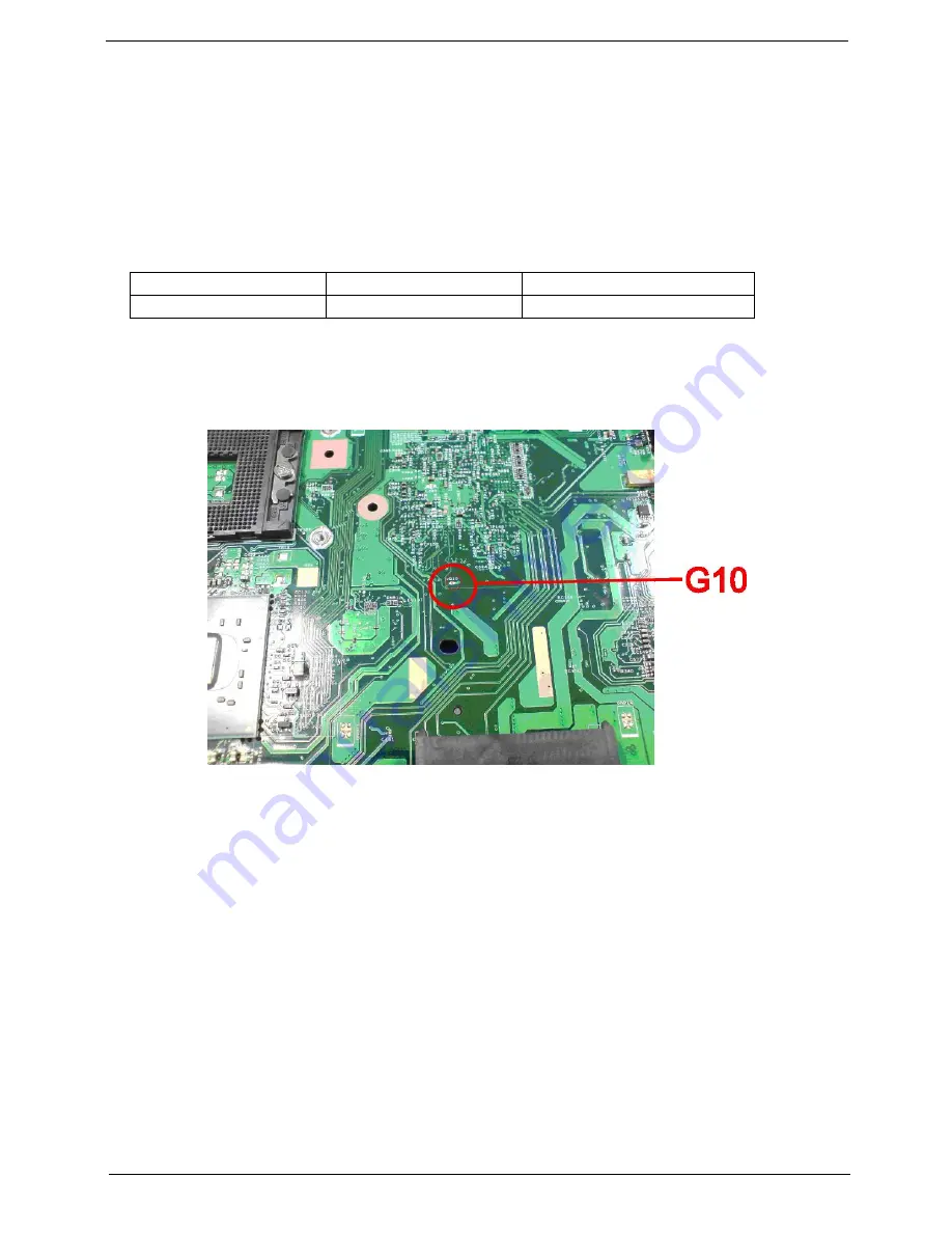
Hardware Open Gap Description
HW Gap position on M/B space:
Gap name in Aspire 5730Z/5330 Series is G10
Steps for Clearing BIOS Password Check
If users set BIOS Password (Supervisor Password and/or User Password) for a security reason, BIOS will ask
the password during systems POST or when systems enter to BIOS Setup menu. However, once it is
necessary to bypass the password check, users need to short the HW Gap to clear the password by the
following steps:
•
Power Off a system, and remove HDD, AC and Battery from the machine.
•
Open the back cover of the machine, and find out the HW Gap on M/B as picture.
•
Use an electric conductivity tool to short the two points of the HW Gap.
•
Plug in AC, keep the short condition on the HW Gap, and press Power Button to power on the
system till BIOS POST finish. Then remove the tool from the HW Gap.
•
Restart system. Press F2 key to enter BIOS Setup menu.
•
If there is no Password request, BIOS Password is cleared. Otherwise, please follow the steps and
try again.
NOTE:
The steps are only for clearing BIOS Password (Supervisor Password and User Password).
Hardware
Default Setting
Operation Description
Gap
Open (Normal)
Short (Clearing Password Check)
Summary of Contents for 5335-2238 - Aspire - Celeron 2.16 GHz
Page 6: ...VI ...
Page 9: ...IX Table of Contents Online Support Information 159 Index 161 ...
Page 10: ...X Table of Contents ...
Page 56: ...46 Chapter 2 ...
Page 102: ...92 Chapter 3 13 Detach any adhesive tapes and any cable that is glued to the LCD panel ...
Page 106: ...96 Chapter 3 12 Remove the Web camera from the back cover ...
Page 120: ...110 Chapter 4 F5h Boot to Mini DOS F6h Clear Huge Segment F7h Boot to Full DOS Code Beeps ...
Page 127: ...Chapter 5 117 Top and Bottom View Jumper and Connector Locations Chapter 5 ...
Page 128: ...118 Chapter 5 ...
Page 132: ...122 Chapter 6 Aspire 5735 5735Z 5335 Series Exploded Diagram ...
Page 145: ...Chapter 6 135 ...
Page 146: ...Appendix A 136 Aspire 5735 5735Z 5335 Series Model Definition and Configuration Appendix A ...
Page 150: ...140 Appendix B ...
Page 152: ...142 Appendix C ...


