AccuTemp EDGE ALTLGB Owner'S Manual And Installation Instructions Download Page 18

Section III:  Service and Maintenance

Gas Control System

Fig. 3.3:  SV9501 / 9502 Gas Control

When to Replace the Gas Control:

√ The gas control does not perform properly on checkout 

or troubleshooting.
√ The gas control knob is hard to turn.
√ The gas control is likely to have operated more than 

200,000 cycles.
√  The control is wet or looks as if it has been wet.

B) Adjusting the Pilot Flame

The pilot flame was adjusted at the factory.  Should it ever 

need adjusting, follow the instructions below.

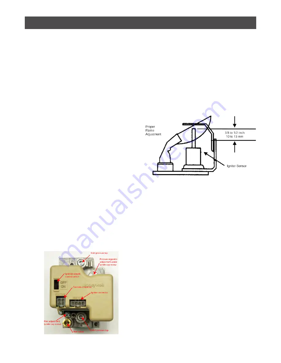
Fig. 3.4:  Pilot System for the SV9501/9502 

SmartValve™ Gas Control

Proper Setting:  The flame should envelope 3/8” to 1/2” 

(10 mm to 13 mm) of the igniter sensor tip.
1. Turn off the thermostat dial.
2. Disconnect the lead to the MV terminal on the gas 

control.
3. Re-light the pilot by turning up the thermostat to call 

for heat.
4. Remove the pilot adjustment cover screw from the gas 

control (see Fig. 3.3).
5. Turn the inner pilot adjustment screw clockwise to 

decrease or counterclockwise to increase the pilot flame.
When done, replace the cover screw and tighten it firmly.

A). Maintenance of the Gas Control System

Your equipment came with an intermittent pilot gas 

control system.  The systems is as follows:
The SV9501/9502 SmartValve™ System Control combines 

gas flow control and electronic intermittent pilot 

sequencing functions into a single unit.  The Q3450 

SmartValve™ System pilot burner provides pilot flame 

ignition and sensing for the SV9501/9502 Systems.  It 

consists of a replaceable igniter-flame rod assembly, 

bracket assembly, pilot target, ground electrode, orifice 

assembly, compression fitting and spring clip.  The igniter 

lights the pilot burner.  The flame rod proves the pilot 

flame and the pilot flame lights the main burner.
Control Knob Settings:
OFF. 

Prevents pilot and main gas flow through the 

ignition system control.
ON. 

Permits gas flow into the control body and, under 

control of the thermostat, to the pilot and main burners.
Frequency of Maintenance Required:
Cycling Frequency.  Appliances that may cycle 20,000 

times annually should be checked monthly.
Intermittent Use.  Appliances that are used seasonally 

should be checked before shutdown and again before 

the next use.
Consequence of Unexpected Shutdown.  Where the cost 

of an unexpected shutdown would be high, the system 

should be checked more often.
Dusty, Wet, or Corrosive Environment.  Since these types 

of environments can cause the gas control to deteriorate 

more rapidly, the system should be checked more often.

16

Summary of Contents for EDGE ALTLGB

Page 1: ...THORIZED SERVICE AGENT EVACUATE ALL PERSONNEL FROM THE AREA WARNING IMPROPER INSTALLATION ADJUSTMENT ALTERATION SERVICE OR MAINTENANCE CAN CAUSE PROPERTY DAMAGE INJURY OR DEATH READ THE INSTALLATION O...

Page 2: ...bly 13 Actuator Maintenance Adjustment 14 Actuator Tension Adjustment 14 Actuator Repacking with Grease 14 Actuator Replacement 14 Fig 3 1 Actuator Components Assembly 15 Fig 3 2 Removing Installing A...

Page 3: ...for safe delivery to the customer until customer acceptance of the package Careful inspection of the packaging and the appliance should be completed before acceptance from the transportation company C...

Page 4: ...de cet appareil ou de tout autre appareil Always disconnect from the power supply and close the main gas valve before servicing The ignition system controls of this equipment have been factory set for...

Page 5: ...a power failure This appliance is equipped with a three prong grounding plug for your protection against shock hazard and should be plugged directly into a properly grounded three prong receptacle Do...

Page 6: ...restrict air movement into the equipment s combustion area or prevent proper combustion Adequate clearance for servicing and proper operation must be maintained Warning This unit is not suitable for...

Page 7: ...sed Connect the supply line to the ball valve at the rear of the unit Tighten the connection securely Electrical Connection A power cord is provided on the back of the unit for connecting to the elect...

Page 8: ...l Inlet Pressure Range Factory Set Nominal Out let Pressure Adjustment Setting Range Intermittent Pilot Natural 5 0 7 0 w c 3 5 w c 3 5 LP 12 0 14 0 w c 9 0 w c 8 12 Checking For Gas Leaks WARNING Do...

Page 9: ...main burner and shut off the gas supply before disconnecting the manometer or pressure gauge by reversing the procedure in Step 2 in the previous procedure for checking the inlet pressure 5 Replace th...

Page 10: ...tact with any electrical and control components For routine cleaning Accutemp s optional Care Kit accessories help you thoroughly clean all surfaces including the inside of the lid and the inside of t...

Page 11: ...mostat Dial Temperature Allows the user to set the cooking temperature of the unit Unit Power On Indicator Light Green Illuminates upon depressing the rocker switch to the ON position This indicates t...

Page 12: ...knob to the ON position and set the primary thermostat dial to the desired temperature setting How to Start Cooking 1 Press the rocker switch to ON position turn the primary thermostat clockwise to th...

Page 13: ...ut breaking the seal and returned to Accutemp The warranty is voided if the seal is broken or any attempt is made to recalibrate a thermostat See below for replacement instructions 1 Disconnect the un...

Page 14: ...ition System Control Disconnect power and turn off main gas supply before starting To replace the gas control valve Item 4 1 Disconnect the controls connector and the igniter connector from the gas co...

Page 15: ...r of burner assembly Item 9 Lift burner out of shroud Reverse steps to replace new burner D Replacing the Pilot Igniter Assembly Refer to steps in C Replacing the Gas Burner or Burner Orifices then Tu...

Page 16: ...ly later 5 Grasp the actuator sleeve and pull down away from the actuator rod The components inside the actuator sleeve will slide out 6 Pack the spring or springs with Bel Ray No Tox Clear Grease 2 T...

Page 17: ...COVER STOP 456695 1 8 Parts List TITLE PART NUMBER QTY ITEM SLEEVE WELDMENT 404483 001 1 1 ROD ACTUATOR LUG 455879 1 2 WASHER NYLON 1 355 X 52 408505 3 3 NYLON SHOULDER WASHER 408506 2 4 NUT SS LOCK 1...

Page 18: ...ilot gas control system The systems is as follows The SV9501 9502 SmartValve System Control combines gas flow control and electronic intermittent pilot sequencing functions into a single unit The Q345...

Page 19: ...sidual steam contained in the steam jacket Remove sight glass and place a funnel in the inlet elbow Pour water into funnel Continue adding water until the Fig 3 5 Examples of Problem Pilot Flames C Id...

Page 20: ...lain end that is not threaded is constructed of a material suitable for exposure to temperatures of 375 F or greater is of a pipe size equal to or greater than that of the valve outlet over its entire...

Page 21: ...er such as Klenzade XY 12 d Film remover such as Klenzade LC 30 Procedure 1 Clean food contact surfaces as soon as possible after use If the unit is in continuous use thoroughly clean and sanitize the...

Page 22: ...se off the sanitizer thoroughly 9 It is recommended that each piece of equipment be sanitized just before use 10 If there is difficulty removing mineral deposits or a film left behind by hard water or...

Page 23: ...stat setting too low Primary thermostat malfunc tioning Air in kettle jacket Uneven cooking due to cold spots Low gas pressure Plugged orifice s in burner Plugged burner supply tube Pilot Outages Low...

Page 24: ...on Pilot burner lights No Measure voltage to SV9500 Voltage must be at least 19 5 VAC No Check transformer line volt supply Yes Yes Main valve opens No Replace igniter sensor assembly and retain Rest...

Page 25: ...CP 1 8 npt 440280 Pigtail anti siphon SS 1 4 npt 456724 Safety relief valve 30 psi 425 lbs hr 3 4 npt Replaces part 440168 456727 Pressure gauge 30Hg 0 60 Replaces part 406732 406578 Terminal Block Ju...

Page 26: ...Section VI Parts List Actuator Parts List Assembly Fig 6 1 Actuator Assembly Diagram 24...

Page 27: ...2 3 1 Nut handle 408392 408392 408207 2 Handle round stainless steel 408359 408359 2 408360 3 Hex bonnet nut 450033 01 450032 01 440234 01 4 Faucet gland 460097 01 410228 01 440233 01 5 O ring 400382...

Page 28: ...ply with these codes Installation 1 Positioning the Unit 3 Verify the voltage requirements and electrical connections were checked Installation 3 Electrical Connection 4 Verify that a sediment trap an...

Page 29: ...the Continental United States and Hawaii They are available 7 days a week from 7 00 a m through 7 00 p m Eastern Standard Time Model No Purchased From Serial No Date Purchased Purchase Order No Locati...

Page 30: ...Wiring Diagram 120V 1PH 28...

Page 31: ...Wiring Diagram 240V 1PH 29...

Page 32: ...RELAY FOR 240 V RED LEAD TO RELAY FOR 208 V BLACK LEAD TO RELAY FOR 120 V TRANSFORMER 24 VOLT YELLOW 24 VAC BLUE 24 VAC BLACK BLACK ORANGE Honeywell 25V GND DIRECT SPARK IGNITION 25V BURNER VALVE VALV...

Page 33: ...rm the repair or replacement This warranty includes travel time not to exceed two hours and mileage not to exceed 50 miles 100 miles round trip but does not include post start up assistance or trainin...

Page 34: ...IMPORTANT SERVICE INFORMATION AccuTemp Product Inc Technical Customer Support Technician is available Monday thru Sunday 7 00am to 7 00pm EST...

Reviews: