background image


Accurate Technology DigiScale Models 18 & 28 User Manual 

Page 33 of 36 

Programming  

Several  functions  of  this  readout  are  user  programmable.    The  following 
describes  what  features  and  functions  are  available  and  how  to  change  the 
factory defaults to customize the system to suit your application needs.  
 

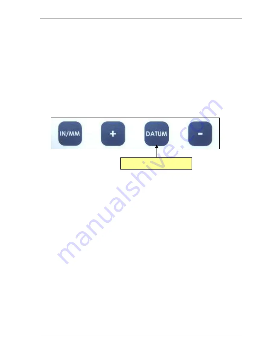
To enter programming mode:  


Press  and  hold  the

  DATUM

  key.  After  approximately  7  seconds  the  readout 

firmware  version  (

b  1.xxx

)  will  be  displayed  for  2-3  seconds  and  then  the 

readout  will  enter  programming  mode.     

PR        1 

is


displayed,


immediately 

followed by the programmed value for Pr1.  Release the 

DATUM

 key.  You are 

now in programming mode. 


Once you are in the Programming mode, momentarily pressing the 

IN

/

MM 

key 

will  advance  through  the  Programming  Parameter  list,  first  displaying  the 
Programming Parameter number, Pr x, then the currently programmed value 
for that parameter. 
 
Momentarily press the 

+ 

key to increase the parameter value setting. 

Momentarily press the 

-

 key to decrease the parameter value setting. 

Momentarily press 

DATUM


to reset the parameter to the factory default value. 


To exit programming mode: 


Press and hold the

 DATUM

 key for 3 seconds.   

 
NOTE:  The  readout  will  automatically  exit  programming  mode  after  60 
seconds of no key activity. 

Press & Hold for 9 seconds 

Summary of Contents for DigiScale 18

Page 1: ...Models 18 28 DigiScale User Manual ...

Page 2: ...Manual Part 800 1404 001 Rev B Page 2 of 36 ...

Page 3: ...ility or fitness for a particular purpose except as expressly provided in this agreement Accurate Technology Inc shall not be liable for any special incidental or consequential damages or for loss damage or expense directly or indirectly arising from the customer s use of or inability to use the equipment either separately or in combination with other equipment or for personal injury or loss or de...

Page 4: ...13 SECTION 3 DIGI READOUT 14 MOUNTING 14 THE LCD 15 CHANGING THE BATTERIES 15 CHANGING THE BATTERIES 16 CALIBRATION 16 CIRCUIT BOARD JUMPERS 17 OPERATION 18 Readout Keys 18 TIMING 18 ON OFF 18 UNITS KEY 18 AND KEYS 19 DATUM KEY 19 Readout Functions 19 REVERSE READINGS 19 INCREMENTAL MEASUREMENTS 20 KEY LOCK 21 RESOLUTION 21 RESTORE READOUT TO FACTORY SETTINGS 21 PROGRAMMING 22 Programming Paramete...

Page 5: ...Y 26 CALIBRATION 26 CIRCUIT BOARD JUMPERS 27 OPERATION 28 Readout Keys 28 TIMING 28 IN MM KEY 29 AND KEYS 29 DATUM KEY 30 Readout Functions 31 REVERSE READINGS 31 INCREMENTAL MEASUREMENTS 31 KEY LOCK 32 RESOLUTION 32 RESTORE READOUT TO FACTORY SETTINGS 32 PROGRAMMING 33 Programming Parameters 34 Pr 1 Datum Key Value 34 Pr 2 Reading Direction 34 Pr 3 Key Lockout 34 Pr 4 Resolution 34 ERROR CODES 35...

Page 6: ...lid state electronic device there s very little to wear out The encoder and scale are designed to withstand shop dirt dust and other airborne contaminants With normal care DigiScale will last for years About This Manual This manual includes theory and INSTALLATION information for DigiScale Models 18 28 Scales and Encoders This manual includes OPERATION information for the Digi and the Compact Read...

Page 7: ...nch 1mm or 01inch 01mm or 001inch 01mm or 1 16 1 32 or 1 64 inch Repeatability 001inch or 01mm Readout Range 999 999 in 399 63 64 in 9999 99 mm Operating Power Digi Readout 2 AA Alkaline Batteries Compact Readout 1 CR123 Lithium Battery Operating Temp 40 to 110 F Slew Rate 60 inches second Encoder cable 72 inch MEASUREMENT range is approximately 4 inches shorter than the PHYSICAL length of the alu...

Page 8: ...rom the scale using a patented technology called inductive coupling This data is then sent to the digital readout where it can be displayed in millimeters inches or fractions Multiple encoders each connected to a digital readout may be used on the same scale simultaneously Models 18 28 encoders have black housings with a cable exiting from one corner The encoder orientation on the scale may be rev...

Page 9: ...ring measurement If you choose this installation proceed to Step 1 However the DigiScale will also operate correctly is the encoder is moved along the scale during measurements If you choose this method proceed directly to Step 2 Note Never drill through the colored portion of the scale at any point over which the encoder will travel 1 Stationary Encoder installation Attach one end of the Connecto...

Page 10: ... underside of the clip engages the post on the top of the encoder and captures it s movement along the scale The guide clip should exert some pressure on the encoder over the full range of travel as the two move as a single unit Insure the scale and encoder are properly aligned as the encoder is moved the guide clip will compensate for slight misalignment in the direction perpendicular to movement...

Page 11: ...coder during measurements however this type of installation is not recommended for the Model 28 Note Never drill through the colored portion of the scale at any point over which the encoder will travel When installing the Model 28 you should use the Guide Clip to capture the encoder movement along the scale see illustrations 1 Attach the scale to a fixed point in your application using the include...

Page 12: ...ndicular to movement Adjust the scale alignment if necessary Plug the encoder cable into the readout Refer to the Digital Readout OPERATION manual that accompanied your DigiScale Typical Model 28 Installation M od el 28 S ca le E n co de r M ov in g P a rt G uide Clip E n c o d e r M o d e l 2 8 S c a le 1 3 8 3 G u id e C li p ...

Page 13: ...could be damaged and the warranty could be voided What does no Enc no Enc no Enc no Enc mean If the encoder is off the scale or unplugged from the readout a no Enc no Enc no Enc no Enc will appear on the readout To clear the error 1 Be sure the encoder is on the scale 2 Plug the encoder into the readout 3 Unplug the encoder from the readout for one second then reconnect it How do I calibrate my Di...

Page 14: ...CD DIGI Part Number 700 1600 D55 With Firmware Version d 2 xxx higher Firmware version is displayed on power up Mounting The Readout may be mounted Using Velcro or Double sided tape Drilling out the 3 holes from the inside of the case Using any of the six holes on the back of the case which may tapped for M2 or 4 40 screws ...

Page 15: ...llustrates all the segments available on the Dig Readout Not all segments are used CAUTION Pressing and holding the ON OFF and UNITS key for 10 seconds with power off will perform a full segment LCD test display the current firmware version and RESET ALL PROGRAMMING PARAMETERS TO FACTORY DEFAULTS ...

Page 16: ...ft corners Pull the cover off Remove the old batteries Reinstall 2 new AA Alkaline batteries noting the proper orientation Replace the cover and tighten the screws CAUTION DO NOT BEND THE BATTERY CLIPS THESE CLIPS ARE DESIGNED TO BE LOOSE WHEN THE CASE IS OPEN AND WILL COMPRESS AND SECURE THE BATTERIES IN PLACE WHEN THE CASE HALVES ARE SCREWED TOGETHER Calibration There is no calibration available...

Page 17: ...r configurable jumpers consisting of three pins and a shorting block or jumper The center of these three pins is Common One end pin is labeled A and the other end pin is labeled B JP1 FACTORY USE ONLY JP2 Programming Lockout Position A Front Panel Programming is ENABLED Position B Front Panel Programming is DISABLED JP1 JP2 ...

Page 18: ...sing the ON OFF key will cause the readout to turn on or off The Firmware Version of the readout is displayed on power up when ON OFF key is used While the readout is on if the encoder is not moved for 15 minutes the readout will automatically turn itself off to conserve battery life While it is off if the encoder is moved as little as 002in 05mm or the ON OFF key is pressed the readout will autom...

Page 19: ...tion by one unit of measurement Momentarily depressing the key decrements the current position by one unit Pressing and holding the or keys will cause the displayed position to change continuously Holding down the key will cause the amount of change to speed up This allows for quick adjustments over a range of large values DATUM KEY The DATUM key forces the readout to display a user programmed val...

Page 20: ...press and hold the UNITS key for approximately 3 seconds The INC INC INC INC symbol will appear in the upper left corner of the display When the INC mode is entered the readout will display zero 0 or the last offset if one was entered and may be changed by using the or keys to provide a different offset Moving the encoder in either direction will display the distance moved from the initial INC sta...

Page 21: ...e permanent Lock function since programming can be disabled with a hardware jumper inside the readout thus preventing any front panel programming changes See Section 3 Programming Programming Parameter Pr3 RESOLUTION The readout can be configured to display measurements in any of three different resolutions 1 Low the resolution is 1in or 1mm 2 Normal the resolution is 01in or 01mm 3 High the resol...

Page 22: ...the current value for the parameter Moving down parameter list Press and hold the ON OFF key then momentarily press the UNITS key to move backward through the Programming list Increase parameter value Momentarily press the PLUS key while displaying a Programming Parameter Value to increase the setting Decrease parameter value Momentarily press the MINUS key while displaying a Programming Parameter...

Page 23: ...ravel positive vs negative when the encoder is moved Default 0 Pr 3 Key Lockout 0 or 1 This parameter controls the operation of the and DATUM keys If enabled set to 1 these keys will not function and the LOCK LOCK LOCK LOCK symbol will appear on the display This prevents accidental changes when pressing these keys during normal operation Default 0 Pr 4 Resolution 1 2 3 or 4 This parameter sets the...

Page 24: ...rmware Version b 2 xxx higher Press the DATUM key for 7 seconds to display Readout Firmware version Mounting Surface Mount Configuration The Compact readout may be mounted Using Velcro or Double sided tape Punch out any of the four holes from the inside of the back case Using any of the four holes on the back of the case NOTE Use a 4 or M3 screw not longer than 3 8 9mm ...

Page 25: ...ner of the front case directly into the panel The rear half of the readout case is not necessary when it is used in a panel mounted configuration with a panel of sufficient thickness to hold the 4 mounting screws If your panel is too thin to hold screws you may sandwich the panel between the front and rear halves of the readout case and install 4 screws long enough to extend through the entire ass...

Page 26: ...place the battery remove the 4 screws in the corners of the readout case Separate the two cases remove the battery clip and the old battery Install a new CR123 3V or equivalent Lithium battery noting the proper orientation Replace the battery clip and rear case half and reinstall the 4 screws Calibration There is no calibration available or necessary for the Compact readout System accuracy will de...

Page 27: ...bled when the shorting jumper is installed on position A To disable programming install it on B When programming is disabled you cannot access the readout programming functions via the front panel as described in the PROGRAMMING This prevents unauthorized or accidental readout configuration changes JP3 Encoder Voltage The Compact readout is used with other Accurate Technology products and systems ...

Page 28: ...e has elapsed for press hold operations See Table Below Momentarily Press Press Hold IN MM Cycles measurement units displayed inches fractions mm 3 seconds Toggles between ABSolute and INCremental modes When in programming mode Cycles program parameter list Has no effect plus minus keys Increments or Decrements displayed value Increments or Decrements displayed value faster DATUM Forces readout to...

Page 29: ...ing the measurement displayed is rounded down to closest 1 16 inch and each illuminated bar would then indicate an additional 1 64 of an inch additional measurement For better measurement precision switch to 1 32 or 1 64 mode For the best precision select a decimal mode in or mm for measurements AND KEYS Momentarily pressing the or key increments or decrements the currently displayed value by one ...

Page 30: ...isplayable value See Section 4 Programming Programming Parameter Pr1 The DATUM key can also be locked out to prevent accidental entries See Section 4 Circuit Board Jumpers JP 2 Additional functions of the DATUM key Press and hold DATUM for 7 seconds to display the firmware version Press and hold DATUM for 9 seconds to enter programming mode Press and hold DATUM for 3 seconds to exit programming mo...

Page 31: ...ode press and hold the IN MM key for 3 seconds The ABS or INC indicator will illuminate on the display While in Incremental mode the and keys are used to set offsets and the DATUM key is used to zero the readout Example of an Incremental Measurement with no offsets 1 Enter the incremental mode press and hold the IN MM key 3 seconds 2 Make a measurement 3 Momentarily depress IN MM or DATUM key to r...

Page 32: ...DATUM and key functions to prevent accidental changes of the currently displayed value To lock these keys set Programming Parameter Pr3 1 See Section 4 Programming Programming Parameter Pr3 RESOLUTION The readout can be configured to display measurements in any of three different resolutions 1 Low the resolution is 1in or 1mm 2 Normal the resolution is 01in or 01mm 3 High the resolution is 001in o...

Page 33: ...tely followed by the programmed value for Pr1 Release the DATUM key You are now in programming mode Once you are in the Programming mode momentarily pressing the IN MM key will advance through the Programming Parameter list first displaying the Programming Parameter number Pr x then the currently programmed value for that parameter Momentarily press the key to increase the parameter value setting ...

Page 34: ...tive vs negative when the measuring system is moved Default 0 Pr 3 Key Lockout 0 or 1 This parameter controls the operation of the and DATUM keys If enabled set to 1 these keys will not function and the LOCK symbol will appear on the readout This prevents accidental changes when depressing these keys during normal operation Default 0 Pr 4 Resolution 1 2 or 3 This parameter sets the number of place...

Page 35: ...6 Unplug the encoder from the readout for 5 seconds and then reconnect What does b FAIL b FAIL b FAIL b FAIL mean When the readout displays this message it means the battery voltage has dropped to a level where reliable operation is no longer possible Install new batteries to clear this message What does P FAIL P FAIL P FAIL P FAIL mean When the readout displays this message it means the battery v...

Page 36: ...UCT Accurate Technology Inc 270 Rutledge Rd Unit E Fletcher NC 28732 USA 828 654 7920 Please register your product at http www proscale com registration htm This manual is available online at www proscale com Part 800 1404 001 Rev B Copyright 2010 Accurate Technology Inc All rights reserved ...

Reviews: