Torque Adjustment
Caution: Load to be removed or blocked. Brake may be
inoperative during this procedure.
The magnetic disc brake is factory set for rated static torque.
The brake can be adjusted to reduce torque which increases
stopping time. Do not attempt to adjust brake for higher
torque, as this will cause premature coil burnout. (Refer to
Fig. 3)
1. To adjust, remove cover locknuts (22) and cover (20)
to expose torque locknuts (15T), which are above
torque springs (15S).
2. To increase stopping time and reduce torque, turn
two locknuts (15T) counterclockwise, increasing
spring length. Each full turn reduces torque 7% to
10% depending upon the model.
Friction Disc Replacement
Caution: Load to be removed or blocked. Brake
will
be
inoperative during this procedure.
If brake model number has a prefix VO or VU, see page 8.
When total wear on a rotating friction disc (13) reaches
1/16”, replace disc:
1.
Removing operator assembly
Disconnect power.
2. Remove cover locknuts (22) and cover (20).
3. Remove operator assembly (15) by removing screws
(16), pivot stud (10), washer (18), bushing (17), and
spring (11).
NOTE: Item (10) has a hex socket in end of stud for
removal. Do not loosen nuts (19) on pivot stud (10),
or “Pivot Stud Adjustment” (on page 6) to quiet the
magnet will have to be made.
4.
Replacing the friction disc
Remove worn rotating discs (13) and stationary discs
(12). Replace worn discs and install new discs in the
same order. Install stabilizer clip (14), if furnished, on
rotating discs prior to installing.
5.
Re-assembly of operator assembly (15)
Refer to Figs. 3 and 9. (Capscrew (16) is shown in
Fig. 9 and not Fig. 3)
Turn two screws (15H) counterclockwise five turns.
Place operator assembly onto brake bracket (2) and
install two screws (16). Replace compression spring
(11), bushing (17), washer (18), and pivot stud (10)
which has the two nuts (19) in place. Tighten firmly.
6. Readjust magnet air gap “A” as described under
“Wear Adjustment” on page 4.
7. Check manual release operation before completing
installation. Adjust per “Manual Release Adjustment”
on page 7 if required.
8.
Completing installation
Replace cover (20) and cover locknuts (22). Tighten
just enough to hold the cover in place. Reconnect
power.
Magnet Assembly Replacement
Caution: Load to be removed or blocked. Brake
will
be
inoperative during this procedure.
1. Disconnect power supply.
2. Remove cover locknuts (22) and cover (20).
3. Remove two capscrews (15D), magnet assembly
(15A) and shock mount (15B).
4. Replace with new magnet assembly (15A), making
sure shock mount (15B) is in place. Feed coil lead
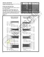
wires through hole in back of bracket (15C) as shown
in Fig. 4. TIghten mounting screws (15D) with 55-60
lb. in. torque.
5. Place coil lead wires around mounting bracket (15C)
to the same side as the wire outlet position. Connect
coil lead wires per “Connection of Coil Leads” and
Fig. 2.
6. Set air gap “A” as described under “Wear
Adjustment” on page 4.
7. Energize coil. Magnet should be quiet; if not, refer to
“Pivot Stud Adjustment” on page 6.
8. Check manual release. If it does not operate properly,
adjust as outlined under “Manual Release
Adjustment” on page 7.
9. Replace cover (20) and cover locknuts (22). Tighten
just enough to hold the cover in place. Reconnect
power.
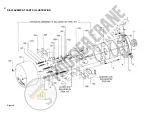
Figure 4
5
Summary of Contents for LOUDEN 200 Series
Page 1: ......
Page 2: ......
Page 3: ......
Page 4: ......
Page 5: ......
Page 6: ......
Page 7: ......
Page 8: ......
Page 9: ...FIGURE 8 FIGURE 9 FIGURE 10 FIGURE 11...
Page 10: ......
Page 11: ......
Page 12: ......
Page 13: ......
Page 14: ......
Page 15: ......
Page 16: ......
Page 17: ......
Page 18: ......
Page 19: ......
Page 20: ......
Page 21: ......
Page 22: ......
Page 23: ......
Page 24: ......
Page 25: ......
Page 26: ......
Page 27: ......
Page 28: ......
Page 29: ......
Page 30: ......
Page 31: ......
Page 32: ......
Page 33: ......
Page 34: ......
Page 35: ......
Page 36: ......
Page 37: ......
Page 38: ......
Page 39: ......
Page 40: ......
Page 41: ......
Page 42: ......
Page 43: ......
Page 44: ......
Page 45: ......
Page 46: ......
Page 47: ......
Page 48: ......
Page 49: ......
Page 50: ......
Page 51: ......
Page 52: ......
Page 53: ......
Page 54: ......
Page 55: ......
Page 56: ......
Page 57: ......
Page 58: ......
Page 59: ......
Page 60: ......
Page 61: ......
Page 62: ......
Page 63: ......
Page 64: ......
Page 65: ......
Page 66: ......
Page 67: ......
Page 68: ......
Page 69: ......
Page 70: ......
Page 71: ......
Page 72: ......
Page 73: ......
Page 74: ......
Page 75: ......
Page 76: ......
Page 77: ......
Page 78: ......
Page 79: ......
Page 80: ......
Page 81: ......
Page 82: ......
Page 83: ......
Page 84: ......
Page 85: ......
Page 86: ......
Page 87: ......
Page 88: ......
Page 89: ......
Page 90: ......
Page 91: ......
Page 92: ......
Page 93: ......
Page 94: ......
Page 95: ......
Page 96: ......
Page 97: ......
Page 98: ......
Page 99: ......
Page 100: ......
Page 101: ......
Page 102: ......
Page 103: ......
Page 104: ......
Page 105: ......
Page 106: ......
Page 107: ......
Page 108: ......


