8
©2015-2017 Acclima, Inc.
Toll Free 1-866-887-1470
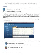
Sensor validation is the final step in the configuration process. It provides a simple way to verify that all configured sensors are
correctly wired into the DataSnap and match the DataSnap’s configuration.
Connect all configured
sensors to the DataSnap and click the ‘Validate’ button. The DataSnap will attempt to find and validate each
of its configured sensors. Sensors that are found and match the DataSnap configuration are annotated with a green check mark.
Sensors that are not found or do not match the configuration show a red X and an error description.
Selecting Acclima Moisture Sensor Locations
Sensors should be located in the region of interest where soil moisture measurements are desired. Acclima sensors measure the
average volumetric water content over the length of the sensor rods. Sensors can be buried in any orientation and will produce
average readings as follows:
•
Flat and Horizontal: Provides a moisture reading at a discrete depth. This orientation is frequently used when monitoring
plants with shallow roots such as turf, or when multiple sensors are used to create a soil moisture profile vs. depth.
•
Vertical: Provides an average moisture reading over a depth of about 6 inches. Often used when monitoring deeper root
systems such as trees.
•
Edge-Horizontal or diagonal: Provides an average moisture reading over a variable depth from 1 to 6 inches.
When selecting a site for sensor placement, consider the following environmental factors:
•
Non-permeable surfaces such as rocks and roads can generate runoff and cause variation in moisture content nearby.
•
Depressions and the base of slopes tend to collect excess moisture.
•
Peaks of slopes, south or west facing hillsides, and areas where reflected light is focused tend to dry out more quickly.
•
If monitoring plant conditions, the sensor must be buried among the roots of the plant of interest. Otherwise, the effects of
transpiration will not be measured.
Installing Acclima Moisture Sensors
The Acclima Soil Moisture sensors report soil moisture as a percentage of the total volume measured. This means that the
measured volume of soil should be free of foreign objects or variations that may alter the measurement made by the sensor.
Consider the following conditions:
•
Avoid placing the sensor near rocks or other similar objects
•
Small roots near the sensor are acceptable. Avoid large woody roots
•
Do not create air pockets or voids near the sensor rods during installation
•
Compact the soil firmly around the sensor rods. Attempt to duplicate the original compaction before the sensor was
installed so that the moisture reading will be representative of the surrounding soil. (Lighter compaction means more air in
the soil which means lower water content by volume since the water is displaced by air).
Wiring Sensors to the SDI-12 port
SDI-12 sensors communicate and draw power from the same wires. They share the connection to the DataSnap
with all other sensors connected to the same DataSnap. This type of a connection is sometimes called
‘
parallel
’
or
‘
bussed
’
. Sensors can be spliced or connected together at a single common point or as taps into a longer run of
wire. Upon wiring completion:
•
every sensor blue wire has electrical contact with the blue
‘D
ata
’
terminal
•
every sensor white wire has electrical contact with the white
‘
Com
’
terminal
•
every sensor red wire has electrical contact with the red
‘
Pwr
’
terminal
Consider the following points when wiring sensors:
•
The maximum wire length from a sensor to the DataSnap is 200 feet.
•
For convenience, the green terminal block can be removed from the SDI-12 port while wires are
connected to it. Simply pull on the block to remove it from the DataSnap. To connect the terminal block, insert it back into
the DataSnap with the screws facing upward.
•
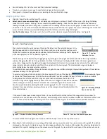
One to two sensors can easily be wired directly into the green terminal block as shown in figure 11. To do this, insert all red
wires into the topmost portion of the terminal block and tighten the screw to secure them in place. Repeat the procedure
for the white wires in the middle portion of the block and the blue wires in the bottom portion of the block. When the block
is connected to the DataSnap, the location of the colored wires must match the colors on the DataSnap.
Figure 5


