background image

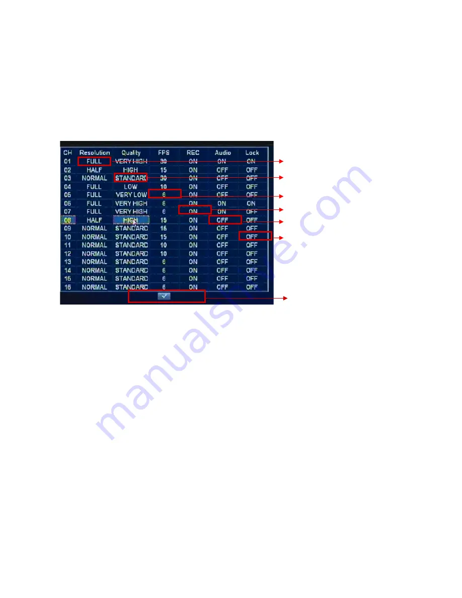
2) REC SETTING

   - 

Resolution

: FULL (4 CIF, D1), HALF(2 CIF, Half D1), NORMAL (CIF)

   - 

Quality

: VERY LOW, LOW, STANDARD, HIGH, VERY HIGH

   - 

FPS:

 30 to 1 FPS.(NTSC)/ 25 to 1 FPS (PAL) 

   - 

REC

: MANUAL, Schedule, EVENT, OFF

   - 

Audio

: ON or OFF

   - 

Lock:

 ON or OFF 


(If “Lock” is ON, this recorded file isn’t be deleted, even though 

                HDD over-writing is done. ) 

NOTE: FPS can automatically changed according to video resolution.

28

Resolution 

Quality ( 5 Level) 

FPS: 

1 to 30 FPS


REC: 

MANUAL/ …/ Off 

Audio: 

On/ Off 

Lock: 

On/ Off 

Exit current GUI

Summary of Contents for ADR-7216

Page 1: ...User Manual Version 1 7 16CH MPEG4 Standalone DVR ADR 7216...

Page 2: ......

Page 3: ...ment on the part of vendor who assumes no liability or responsibility for any errors that may appear in this manual This manual contains materials protected under International Copyright Laws All righ...

Page 4: ...15 4 3 SYSTEM 17 4 4 DISPLAY 25 4 5 RECORD 27 4 6 EVENT 29 4 7 SCHEDULE 31 4 8 NETWORK 33 4 9 COPY BACKUP 36 4 10 HARD DISK 37 4 11 CAMERA 39 Section5 Searching for Playback 41 Section6 Live Display...

Page 5: ...rveillance 1 2 Features MPEG4 compression format D1 resolution 16ch all real time recording display eSATA interface for external storage expansion Multiple recording modes User friendly GUI Multi lang...

Page 6: ...detection Yes Power DC 12V 7A Dimension 430 W x 88 H x 340 D mm 1 4 Package Digital Video Recorder ADR 7216 1 Power Adapter 1 Power Cord 1 Support CD including PC_SW User Manual IR Remote Controller 1...

Page 7: ...still picture 3 LED Indicators 1 POWER This red LED turns ON when Power is ON 2 NET This green LED will turn ON while data through network is transmitting 3 COPY This green LED will turn ON during da...

Page 8: ...button Backup This COPY button can be used to retrieve some of recorded files into backup media like USB memory drive or CD DVD after searching recorded files NOTE the media for backup USB memory dri...

Page 9: ...rection button and Enter Button Direction buttons are used to move LEFT RIGHT UP and DOWN in menu They also can be used to input password ENTER button is used to save parameter to select parameter in...

Page 10: ...tputs can be utilized for it 4 5 16CH Audio input RCA and 2CH Audio Output RCA Unbalanced audio signal input and output with RCA jack Connect the audio source to audio input audio output to your ampli...

Page 11: ...d connectors The threshold voltage is 4 3V and should be stable at least 0 5 seconds to be detected 2 G Ground COM common Connect the ground side of the Alarm input to G Ground Connect the ground side...

Page 12: ...osen the screws The screws are located at the top 1 on the sides 4 and at the back 2 of DVR as indicated by the red circles Remove the screws and keep them in a safe place for latter use Once the uppe...

Page 13: ...on2 SATA HDD 3 DVD RW 1 Two internal SATA HDDs must be connected to SATA3 and SATA4 as shown in the picture To add another internal SATA HDD connect it to SATA1 as shown in the picture The DVD RW must...

Page 14: ...HDD rack then install the HDD in place as shown below using the screws Once the HDDs are installed into the HDD racks place the racks back align them with the holes on the chassis and tighten the scre...

Page 15: ...t it as the two part shown as below Position the two mounting plates on either side of the DVD RW then tighten them with screws Now place the assembly inside the DVR chassis align the mounting plates...

Page 16: ...MERA HDD COPY NETWORK 9 8 7 6 No NAME ICON SCHEDULE 5 EVENT 4 RECORDING 3 DISPLAY 2 SYSTEM 1 NAME ICON No Menu Icons CAMERA HDD COPY NETWORK 9 8 7 6 No NAME ICON SCHEDULE 5 EVENT 4 RECORDING 3 DISPLAY...

Page 17: ...ADE FACTORY RESET VERSION NO DATE TIME SET DATE FORMAT TIME FORMAT ADMIN LOCK PASSWORD VIDEO FORMAT LANGUAGE CAMERA 9 HDD 8 COPY 7 NETWORK 6 SCHEDULE 5 EVENT 4 RECORD 3 DISPLAY 2 SYSTEM 1 NTP TIME SYN...

Page 18: ...YES factory default is YES below figure will be appeared Then input password number using 1 2 3 9 Channel Buttons Factory default password is 11111111 and press ENTER button MAIN MENU will be appeared...

Page 19: ...LANGUAGE The OSD language which can be displayed in Menu can be selected Whenever left or right button is pressed supported language can be selected For language selection by graphical user interface...

Page 20: ...er is ON after camera s connection for video format recognition 3 PASSWORD Move Highlight icon to PASSWORD in the SYSTEM Menu using DOWN or UP button And press ENTER button to change password Then bel...

Page 21: ...nt functions for each user SUB USERS of SYSTEM SETUP MENU can be selected The detail function selection for each SUB USER can be done like below There are SETUP for MENU configuration setup SEARCH for...

Page 22: ...DMIN s password 11111111 The modification for each sub user can be followed by specific user selection in MENU NOTE The SETUP for MENU configuration setup for the user should be On by ADMIN in advance...

Page 23: ...by manual or mouse at first If it set as Off DVR receives all the remote controller signal It means that DVR don t use remote ID Factory initial setting is Off Remote ID function This remote controlle...

Page 24: ...ock Icon on the left top side of monitor NOTE Remote Controller Lock function can be set only in live picture mode 7 TIME FORMAT 24 12 HOURS Move Highlight icon to TIME FORMAT in the SYSTEM Menu using...

Page 25: ...moved to DATE or TIME using DOWN or UP button The movement to year month day is done by LEFT or RIGHT button The year change can be done by DOWN or UP button Month day can be adjusted as same way Aft...

Page 26: ...tail information Please see Section9 F W Upgrade NOTE When all of menu setting are finished escape menu mode below figure SAVE which ask to save all the setting will be appeared If all the menu settin...

Page 27: ...POT DWELL 1 to 60 seconds SPOT DWELL TIME can be changed using LEFT or RIGHT button Or after pressing ENTER button SEQ DWELL TIME from none 1 seconds to 60 seconds which decide a period of channel by...

Page 28: ...els Total period of POP UP display is 30 seconds 7 ADJUST CH CH1 CH2 CH3 CH4 CH16 The camera channel needed to adjust brightness contrast Hue Saturation can be selected 8 PRIVATE The video channel whi...

Page 29: ...y unauthorized person intentionally The STOP KEY DISABLE ENABLE can be changed using LEFT or RIGHT button Or after pressing ENTER button STOP KEY DISABLE ENABLE can be selected by UP or DOWN button An...

Page 30: ...C 25 to 1 FPS PAL REC MANUAL Schedule EVENT OFF Audio ON or OFF Lock ON or OFF If Lock is ON this recorded file isn t be deleted even though HDD over writing is done NOTE FPS can automatically changed...

Page 31: ...QUALITY FRAME RATE DURATION can be selected separately 1 Event Setup1 parameter Setting 29 EVENT Setup1 Selection EVENT Setup2 Selection MotionArea CH selection MotionArea Selection Exit this menu Du...

Page 32: ...e mark motion area can be enabled by direction button In the mark motion area can be disabled by direction button Motion channel can be changed by or button from CH1 to CH16 30 Motion Area CH selectio...

Page 33: ...f SCHEDULE is selected by ENTER button below Schedule Select will be appeared 1 OFF or Weekly SET or Daily SET can be configured in Schedule Select It can be selected by LEFT or RIGHT button OFF means...

Page 34: ...If Daily SET is selected below figure will be appeared It is also possible to configure ALARM MOTION and MANUAL together in Daily SET figure as Weekly SETUP Each mode from ALARM MOTION to MANUAL can...

Page 35: ...or RIGHT button Or after pressing ENTER button STATIC or DHCP can be selected by UP or DOWN button And then ENTER button is used for confirming setting value 2 IP ADDRESS 3 SUBNET MASK 4 GATEWAY 5 DNS...

Page 36: ...er to save the assigned number of IP address and so on Yes should be selected by ENTER button in check box 6 PORT Port number for TCP IP connection in DVR Net Viewer software should have same port Num...

Page 37: ...is not set properly in fixed IP address this function will not be operated 9 DDNS STATUS Dynamic DNS status display This DDNS status is just readable It is recommended not to use this DDNS service for...

Page 38: ...BACKUP log file you can see BACKUP log information using Word Pad of PC ENTER button is used to start the BACKUP of LOG data If there is no BACKUP media No BACKUP media message will be appeared 3 CD...

Page 39: ...figure will be appeared 1 OVERWRITE HDD OVERWRITE can be used for repetitive recording in to same HDD space First recorded area in HDD can be replaced with new recording data OVERWRITE can be selected...

Page 40: ...support quick HDD format function In order to format HDD in FORMAT HDD after pressing ENTER button YES or NO can be selected by LEFT or RIGHT button for HDD format 3 INFO It shows total HDD capacity...

Page 41: ...r selecting CAMERA NO first for CAMERA ID changing CAMERA ID can be changed by OSD keyboard of below figure When ENTER button is pressed below figure will be appeared Movement in OSD keyboard can be d...

Page 42: ...ng function would be connected with some of video inputs The camera s has have its own control protocol needed to control panning tilting and zooming according to PTZ camera manufacturer NOTE PTZ stan...

Page 43: ...reeze picture in playback PLAY PAUSE button is used The movement of single field in still picture mode can be fulfilled by LEFT or RIGHT button And Jog and shuttle dial also enable user to use FF REW...

Page 44: ...CD or DVD It is displayed in left top on monitor BACKUP It is displayed in left top on monitor PTZ It is displayed in left top on monitor Network It is displayed in left top on monitor Key Lock Manua...

Page 45: ...g using UP or DOWN button According to selection of recording type recorded files will be listed in below calendar After moving to Date using LEFT or RIGHT button searching day in calendar can be chan...

Page 46: ...Below GUI will be appeared The channel s which want to copy can be selected here According to channel selection information about total file size to be copied will be shown 5 It will start to copy the...

Page 47: ...lection button from CH1 to CH16 in front panel of DVR b Press PTZ button to select PTZ mode PTZ MODE OSD will be displayed on upper right corner of monitor c Use UP DOWN button for up and down movemen...

Page 48: ...port in front panel of DVR 3 Press MENU button 4 Select SYSTEM SETUP menu in main menu 5 Move to UPGRADE of SYSTEM SETUP Press ENTER button of front panel in your DVR Below GUI will be appeared For f...

Page 49: ...mpleting F W upgrade your DVR will be automatically rebooted 7 F W Upgrade Completion S W upgrade version will be seen on VERSION NO of SYSTEM SETUP CAUTION It will take about 10 15minute to finish F...

Page 50: ...r viewer software has been already installed on your computer you should uninstall the software first Please follow below steps to finish client software installation 48 1 Insert the installation CD 2...

Page 51: ...ion style in following dialog box Complete can selected for normal installation And then click Next 5 Please wait for a while 6 Installation is finished And Net_View File_Player and CMS icon will be s...

Page 52: ...ting zooming and focusing 3 Remote Setting for menu configuration 5 Remote Searching 12 Capture Start for single picture printing and saving 11 Recording in local PC 10 Audio Mute ON OFF 8 Microphone...

Page 53: ...can be written in ADDRESS This IP address can be confirmed in IP address of NETWORK menu in DVR PORT number default is 10000 It can be changeable according to network environment USER is assigned as...

Page 54: ...move it C How to modify CONNECT ADDRESS First select one of listed ADDRESS which want to modify and modify one of NAME ADDRESS usually Then click MODIFY to modify it D How to CONNECT Network Select on...

Page 55: ...Focus Near Move to Left and move to Left Down Move to Right Up and move to Left Focus Far Focus Zoon In Zoon Out Zoom Move to Down and move to Down Right Move to Left Up and move to Up Pan and Tilting...

Page 56: ...elow sub window will be appeared with motion or alarm information like Motion Event CH3 18 18 59 if VIEW is clicked the channel with motion detection or alarm triggering will be displayed as single pi...

Page 57: ...configured data in remote DVR If it is not requested to reflect configured data in DVR just CLOSE icon can be clicked B Display configuration SELECT CH All of 16ch video quality including brightness c...

Page 58: ...e its own control protocol needed to control panning tilting and zooming according to PTZ camera manufacturer In order to control the camera with PTZ function in network viewer software remotely PTZ T...

Page 59: ...ch don t have to record can be selected as OFF after selecting channel in SELECT CH RECORD SCHEDULE Weekly Schedule recording or Monthly Schedule recording can be selected for schedule recording If No...

Page 60: ...mally it store 5 seconds in D1 resolution for each channel TRIGGER OUT It defines the selection of trigger output from trigger out1 to 4 when motion or alarm is detected in some of channels Duration I...

Page 61: ...detection or alarm triggering within reserved time Schedule recording by Record in red mark will be started in reserved time zone NOTE The recording reservation by event motion or alarm is represented...

Page 62: ...selected in It is used for repetitive recording in to same HDD space First recorded area in HDD can be replaced with new recording data 1 2 3 1 2 3 1 REMOTE SEARCH can be utilized for not only searchi...

Page 63: ...ct date for PB Select channel for PB Select hour for PB Select minute for PB Click Play for playback PB 2 3 4 5 6 2 6 If mouse button is double clicked Small picture will be changed and vice versa Dis...

Page 64: ...ared as below figure SAVE or PRINT icon can be selected for either picture saving or picture printing File download Select date for PB Select channel for PB Select hour for PB Select minute for PB Cli...

Page 65: ...cture saving path will be requested as below figure The file format for saving single picture is standard JPEG 2 When PRINT icon is pressed below sub GUI of PRINT will be appeared and picture printing...

Page 66: ...icon If RECORD icon is pressed again recording will be stopped with dark RECORD icon 1 2 3 For two way audio communication the activation of microphone will be needed MIC ON icon can be pressed for Mi...

Page 67: ...arm is are triggered in any remote DVR event information will be noticed to NetViewer as below picture NetViewer shows additional Alarm Motion Window with corresponding event information As well as al...

Page 68: ...on is clicked default directory C DVR BACKUP will be shown The directory related to backup media like USB or CD can be searched in there For example DVR or CD R W drive is E For file playback searched...

Page 69: ...olled The directory to save live video or backup video also can be changed by user 6 Volume Control and mute For audio playback with video single channel which want to listen should be selected first...

Page 70: ...selected for full screen display by single channel select 10 Capture CAPTURE procedure Step1 Click CAPTURE icon Step2 Then this GUI will be appeared Click SAVE icon 68 CH16 CH15 CH14 CH13 CH12 CH11 C...

Page 71: ...d in most of PC CAPTURE procedure 69 Step1 If MPEG 4 to AVI file conversion is clicked left figure will be appeared Step2 select file path including MPEG 4 file which is needed to convert into AVI fil...

Page 72: ...splay 2 PTZ control for Pan tilting zooming and focusing 3 Remote Setting for menu configuration 5 Remote Searching 12 Capture Start for single picture printing and saving 11 Recording in local PC 10...

Page 73: ...P for multiple DVR monitoring 71 When CONNECT icon in main Window of CMS is clicked below CONNECT GROUP window will be appeared Add Group procedure is like to 1 3 1 2 Click Add Group Fill Group name C...

Page 74: ...Group is selected same Group name will be appeared NAME MTG rm ADDRES 16777009 goddns org PORT 10000 USER admin PASSWORD 11111111 View Channel CH1 CH4 Select the Channel which you want to view in CMS...

Page 75: ...B How to delete DVR in selected group C How to modify DVR in selected group 73 Click DELETE 2 First click what to delete 1 Click MODIFY 3 First click what to modify 1 Modify what want to modify 2...

Page 76: ...D How to start CMS monitoring 74 1 Click Group Click CONNECT for CMS monitoring 2...

Page 77: ...to delete group F How to modify Rename group 75 First Select the Group which want to delete 1 Click Delete Group 2 First Select the Group which want to delete 1 Click Modify Group 3 Rename the Group n...

Page 78: ...le clicked below detail items will be appeared 1 Any item of one Group can be easily moved to another Group by drag and drop of mouse after selecting one of any items in a Group When DISCONNECT is cli...

Page 79: ...noticed to CMS software as below picture CMS software shows additional vent Window 13 E MAP function In main GUI of CMS software if E MAP icon is clicked below default E Map will be appeared The path...

Page 80: ...Pin description Pin NO SHIELD 5 GND 4 D TX 3 D TX 2 VCC 1 Pin description Pin NO 1 USB Pin Descriptions Front panel 2 VGA Pin Descriptions 1 15 1 5 GND 1 GND 4 RS485 D TX 3 RS485 D TX 2 Pin descripti...

Page 81: ...GND Common 10 Sensor input 08 9 Sensor input 07 8 Sensor input 16 19 GND Common 20 Sensor input 15 18 Sensor input 14 17 Sensor input 13 16 GND Common 15 Pin description Pin NO GND Common 6 Relay outp...

Reviews: