34
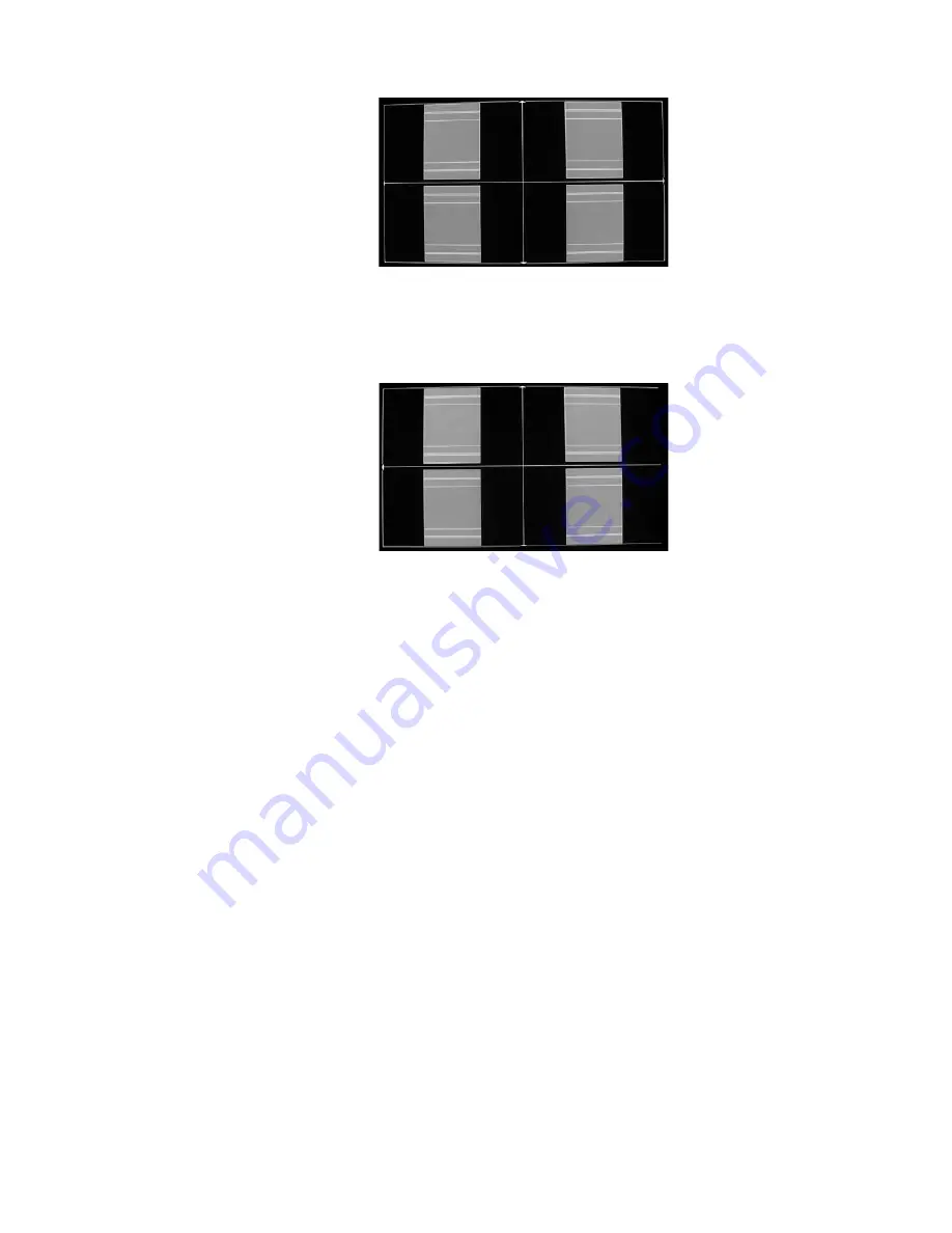
Frame/Geometry Test Pattern Displayed Correctly (Image B)
When this test pattern is displayed correctly, it should look like this, with a one-pixel wide white
border around the edge of the screen:
Frame/Geometry Test Pattern (Image C)
As shown in image C, the test pattern is almost displayed correctly. You can see the 1-pixel wide
white border on the top, bottom and left side of the image but not on the right side of the image.
By adjusting the horizontal size of this signal to 1360 (rather than 1366), you can get this test pattern
displayed correctly on the display.
To change the horizontal size of the image, you must first put the iScan in ‘Advanced’ user mode.
Configuration
_
user Mode
_
Advanced
output setup
_
format
_
H-Size
_
1360
In some cases, the output format is correct, but the image just needs to be shifted to fill the screen
correctly. Do this by using the Horizontal and Vertical Shift options in the ‘Output Setup’ menu.
output setup
_
format
_
366x768
_
H-Shift
_
range
output setup
_
format
_
366x768
_
V-Shift
_
range
NOTE:
Any adjustments made to the output format change your selected output from the resolution
you selected to ‘User’. This allows you to adjust the output without affecting the default settings.
There are three test patterns used to verify that the chosen output resolution is the native resolu
-
tion of your display and that you are bypassing any internal processing in your display. They are the
checkerboard, vertical lines and horizontal lines test patterns.
When the checkerboard test pattern is displayed correctly, close up you should be able to see a
1-pixel checkerboard and at proper viewing distance the image should appear as an even gray. If your
display is CRT-based you will not see this checkerboard, but your screen should be an even gray.


