


E-PGM+ / E-GANG4/6 / E-PGM Serial User’s Manual
2. Hardware
9
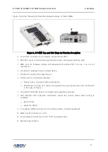
Figure 3 and the following list describe external features of the E-PGM+:
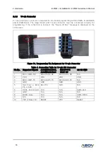
Figure 3. E-PGM+ Top and Side Views for Function Description
①
10-pin IDC connector for In-System Programming (ISP)
②
RS-232C serial communication port (External bar code reader interface port)
③
SWD port for firmware update and development purpose (Do not use, it is not for
customers.)
④
A button for programming the target device
⑤
A button for reading the target device
⑥
LCD Screen for Information Display:
—
Device name, checksum data and options.
—
PASS/FAIL is shown as a result of programming, accompanied by error information
in the case of failure.
⑦
40-pin DIP TEXTOOL Socket for single chip programming mode.
⑧
LED Indicator with red/green illumination shows the current status when writing is
complete:
—
Red for FAIL
—
Green for PASS
⑨
5-pin Molex 5264 connector for the interface with a Handler equipment
⑩
USB mini-B connector to a PC
⑪
Power Adaptor Connector for the 15V/1A external power
⑫
System Power Switch


