


Ap1200 Users’ Guide Page 11 of 14
6
CONNECTING UP TO A PERSONAL COMPUTER
6.1
SUGGESTED CONNECTIONS TO A PC
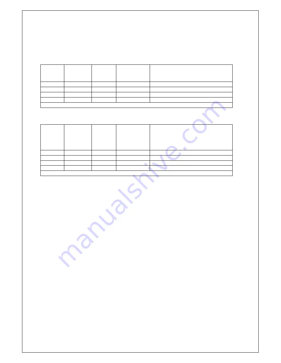
To operate from a PC, you will need a cable to connect from the Ap1200 J2 connector to a serial
COM port on the PC. These COM ports can be either 9-Pin or 25-Pin type. For connections to a 9-Pin
COM port see Table 1. For connections to a 25-Pin COM port see Table 2.
Table 1
Ap1200
J2 Pin
Ap1200
Signal
Name
PC D-9
Pin
PC Signal
Name
Function (refers to PC)
2
RXD
3
TXD
Transmit Output (RS 232)
4
TXD
2
RXD
Receive Input (RS 232)
1
SGND
5
SGND
Signal Ground
3
BUSY
6 & 8
DSR & CTS
Busy Input (RS 232)
Other pins are unconnected
Table 2
Ap1200
J2 Pin
Ap1200
Signal
Name
PC D-25
Pin
PC Signal
Name
Function (refers to PC)
2
RXD
2
TXD
Transmit Output (RS 232)
4
TXD
3
RXD
Receive Input (RS 232)
1
SGND
7
SGND
Signal Ground
3
BUSY
5 & 6
DSR & CTS
Busy Input (RS 232)
Other pins are unconnected
It is strongly recommended that a screened data cable be used, with its braided screen connected to
the system ground.
6.2
GETTING STARTED
You may find that you can connect up the printer to your Personal Computer (PC), and everything
works perfectly first time. However, there are many variables, and the following guide may help if you
find you need some assistance. These are only suggestions, and may not work with all PC’s.
Connecting To A PC
•
First, you need to
GET THE PRINTER GOING
Before trying to send data to it from your computer, it may be a good idea to check that the printer
works by itself.
Before handling the pre-production Ap1200 printer please ensure that you are fully discharged.
•
Connect the unit to a suitable power supply as defined in the section 'Power Supply Requirement'.
•
The green LED indicator should come on (possibly flashing).
•
Ensure paper is loaded (see section 'Changing The Paper')
•
Press the feed button to check that paper feeds.
•
Press the paper feed button again twice in quick succession (like double-clicking a PC mouse)
and the printer should print a self-test message. This will show that the printer is operational, and
also reports the way in which the printer’s serial data interface is configured.
•
Next, you need to make some
HARDWARE CONNECTIONS
The back panel of a PC normally includes three D-type (keystone-shaped) connectors, typically as
follows:
D-9 Plug (male): COM1: Serial port for mouse, serial printer, etc
D-25 Plug (male): COM2: Serial port for modem, serial printer, etc
D-25 Socket (female): LPT: Parallel (‘Centronics’) port for parallel printer, etc
Section Continues...


