background image

BIOS Setup 

3-5 

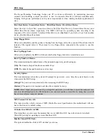
The Hyper-Threading Technology helps your PC work more efficiently by maximizing processor 
resources and enabling a single processor to run two separate threads of software simultaneously, 
bringing forth greater performance and system responsiveness when running multiple applications at 
once. 

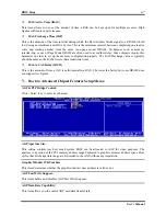
First Boot Device / Second Boot Device / Third Boot Device / Boot Other Device: 

Select the drive to boot first, second and third in the [First Boot Device], [Second Boot Device], and 
[Third Boot Device] items respectively. The BIOS will boot the operating system according to the 
sequence of the drive selected. Set [Boot Other Device] to [Enabled] if you wish to boot from another 
device other than these three items. 

Swap Floppy Drive: 

When set to [Enabled], and the system is booting from the floppy drive, the system will boot from drive B 
instead of the regular drive A. There must be two floppy drives connected in the system to use this 
function. 

Boot Up Floppy Seek: 

When set to [Enabled], the BIOS will check whether the floppy disk drive is installed or not. 

Boot Up NumLock Status: 

This item determines the default state of the numeric keypad at system booting up. 

[On]:

 The numeric keypad functions as number keys. 

[Off]:

 The numeric keypad functions as arrow keys. 

Security Option: 

This item determines when the system will prompt for password - every time the system boots or only 
when enters the BIOS setup. 

[Setup]: 

The password is required only when accessing the BIOS Setup. 

[System]: 

The password is required each time the computer boots up.


NOTE:

 Don’t forget your password. If you forget the password, you will have to open the computer case 

and clear all information in the CMOS before you can start up the system. But by doing this, you will 
have to reset all previously set options. 

MPS Version Ctrl For OS: 

This item specifies which version of MPS (Multi-Processor Specification) this motherboard will use. 
Leave this item to its default setting. 

OS Select For DRAM > 64MB: 

This item allows you to access the memory that is over 64MB in OS/2. Leave this item to its default 
[Non-OS2] setting for operating system other than OS/2. 

Disable Unused PCI Clock: 

This option disables the clock of PCI slot that is not in use. 

User’s Manual 

Summary of Contents for SG-72

Page 1: ...SG 72 Socket 478 System Board User s Manual 4200 0396 01 Rev 1 00 ...

Page 2: ...ental or consequential damages arising from any defect or error in this manual or product Product names appearing in this manual are for identification purpose only and trademarks and product names or brand names appearing in this document are the property of their respective owners This document contains materials protected under International Copyright Laws All rights reserved No part of this ma...

Page 3: ...s and Switches 2 4 1 ATX Power Input Connectors 2 4 2 FAN Connectors 2 5 3 CMOS Memory Clearing Header 2 6 4 BIOS Protection Header 2 7 5 Front Panel Switches Indicators Header 2 8 6 Floppy Disk Drive Connector 2 9 7 IDE Connectors 2 10 8 Internal Audio Connectors 2 11 9 Accelerated Graphics Port Slot 2 11 10 Additional USB Port Headers 2 12 11 Additional COM2 Port Header 2 13 12 Front Panel Audio...

Page 4: ...Frequency Voltage Control 3 16 3 9 Load Fail Safe Defaults 3 16 3 10 Load Optimized Defaults 3 16 3 11 Set Password 3 16 3 12 Save Exit Setup 3 16 3 13 Exit Without Saving 3 16 Chapter 4 Driver Installation 4 1 4 1 Setup Items 4 2 Appendix A Troubleshooting Need Assistance A 1 Appendix B How to Get Technical Support B 1 SG 72 ...

Page 5: ...1 1 User s Manual User s Manual ...

Page 6: ... 設計 的散熱套件及散熱片 1 請在主機板上面找出 Socket 478 插座的位置 然後將固定模組基座固定在主機板上面 注意 如果您使用專門為英特爾 Pentium 4 處理器 所設計的機殼 請注意已經安裝在機箱上的金屬螺 栓或是間隔卡樁 請小心不要讓金屬螺栓或是間隔 卡樁接觸到印刷電路板上的線路或是零件 2 請將處理器插座的釋放拉桿向插座的外側拉 出 然後將釋放拉桿以 90 度角的角度向上拉 起 然後請您以正確的方向將處理器插入處理 器插座 切勿太過施力地將處理器置入插座 因為您只能以一個固定的方向來將處理器插 入 當處理器置入到處理器插座之後 請將插 座釋放拉桿再下推到底即可 3 請將散熱片面朝下地置放到處理器的上面 直 到散熱片完全地蓋住處理器為止 4 將風扇及其固定架機構組件覆蓋至散熱片上 面 請確認風扇及其固定架機構組件四個邊角 的鎖扣都已經卡入固定架的鎖孔位置 5 將風扇以及...

Page 7: ...入 DIMM 模組 5 要取出 DIMM 模組 請您向外側同時地壓下 DIMM 插槽兩側的模組固定夾 即可將 DIMM 模 組抽取出來 注意 靜電會造成電腦或是附加卡上電子元件的損壞 在您要進行這些程序之前 請確認您已經藉 由暫時地接觸已接地的金屬物體來放掉您身上所帶有的靜電 連接器 連接頭以及附加卡的安裝 在任何一部電腦機殼的裡面 都必需連接一些纜線與插頭 這些纜線與插頭通常都是一對一的連接 至主機板的連接埠上 您必需注意任何一條纜線的連接方向 如果可能的話 請一併注意連接埠第 一根針腳的位置 您將會安裝一些特殊功能的附加卡到主機板上面 像是 SCSI 卡或是 AGP 顯示 卡等等 當您將它們安裝到主機板上適當的插槽之後 請以螺絲將這些附加卡與機殼背板牢牢地固 定好 避免有鬆動的情況發生 如您想要瞭解相關且更為詳細的資訊 請參閱我們的完整版使用手冊 裡面會有詳盡的說明 將電源供應器的電源...

Page 8: ...別に設計されたキットをお求 めください 1 マザーボードに 478 ピン ZIF ソケットが見つ かったら リテンションモジュールをマザー ボードに固定します 注意 Pentium 4 マザーボードの用に特別に設計 されたシャーシをご使用の場合 金属製スタッド やスペーサーがすでにシャーシに取り付けられ ていれば その場所に注意してください 金属製 スタッドやスペーサーが PCB の印刷回路線や部 品に接触しないように用心してください 2 ソケットから CPU のソケットレバーを横に それから 90 度上に引っ張ります CPU を正 しい方向に差し込みます CPU は一方向にし かフィットしないため CPU を差し込む際に 余分な力をかけないでください CPU を押さ えながらソケットレバーを閉めます 3 ヒートシンクを CPU にすっぽりかぶせます 4 ファンとリテンションメカニズムアセ...

Page 9: ...DIMM モジュールは一 方向にしかフィットしません 5 DIMMモジュールは スロットの2つのイジェクタタブを外側に同時に引っ張ると外れます 注意 静電気はコンピュータやオプションのボードの電気コンポーネントを損傷させることがあ ります これらの手順を開始する前に アースされた金属物体に軽く触れて静電気を必ず放電し てください コネクタ ヘッダ スイッチおよびアダプタ コンピュータのケース内部には 複数のケーブルやプラグを接続できます これらのケーブルや プラグは 通常マザーボードにあるコネクタに 1 つずつ接続されます ケーブルの接続方向には 十分な注意を払い また必要に応じ コネクタの第 1 ピンの位置にも注目する必要があります SCSI アダプタ AGP アダプタのような特殊なニーズ向けには それに対応したアダプタを取り 付けてください アダプタをマザーボードのスロットに取り付けた...

Page 10: ...4 konstruiertes Gehäuse verwenden achten Sie bitte auf die Lage der Metallbolzen bzw Abstandhalter wenn sie schon im Gehäuse installiert sind Achten Sie darauf dass kein Kontakt zwischen Metallbolzen bzw Abstandhalter und den gedruckten Schaltkreisen bzw leitfähigen Teilen auf dem PCB entsteht 2 Ziehen Sie den Hebel des Prozessorsockels seitwärts vom Sockel und dann im 90 Grad Winkel nach oben Set...

Page 11: ...n es paßt nur in eine Richtung hinein 5 Zum Ausbau der Module drücken Sie die beiden Auswurflaschen auf dem Steckplatz nach außen zusammen und ziehen das Modul heraus Anschlüsse Sockel Schalter und Adapter Im Inneren des Gehäuses findet man in jedem Computer viele Kabel und Stecker die angeschlossen werden müssen Diese Kabel und Stecker werden normalerweise einzeln mit den Anschlüssen auf der Haup...

Page 12: ...r la carte mère Serrez la Base du Module de Rétention sur la carte Attention Si vous utilisez un châssis spécialement conçu pour Pentium 4 veuillez faire attention à l emplacement des Clous en Métal ou des Espaceurs installés sur le châssis Ne laissez jamais les Clous en Métal ou les Espaceurs entrer en contact des circuits imprimés ou des composants sur le PCB 2 Tirez le levier du socle CPU sur l...

Page 13: ...ommager les composants électroniques de l ordinateur ou des cartes optionnelles Avant de commencer ces procédures assurez vous de bien décharger toute l électricité statique en touchant rapidement un objet métallique relié au sol Connecteurs Socles de connexion Interrupteurs et Adaptateurs A l intérieur du boîtier de n importe quel ordinateur il y a plusieurs câbles et prises qui doivent être conn...

Page 14: ...имание Устанавливая плату в корпус разработанный специально для Pentium 4 обратите внимание на уже установленный крепеж металлические стойки зажимы Убедитесь что установленный крепеж не касается системной платы или ее выводов 2 Оттяните рычаг фиксации процессора в сторону и поднимите его на 90 градусов вверх Расположив процессор соответствующим образом вставьте его в разъем Не прилагайте излишних ...

Page 15: ...ите модуль Внимание Статическое электричество может стать причиной выхода из строя электронных компонентов компьютера Перед началом данной процедуры снимите с себя статический заряд коснувшись заземленного металлического предмета Разъемы переключатели и адаптеры Внутри корпуса компьютера необходимо расположены несколько кабелей и вилок которые необходимо подключить Обычно эти кабели подключаются к...

Page 16: ...prega prestare attenzione all ubicazione delle guarnizioni metalliche o degli spaziatori nel caso in cui siano già installati sul telaio Assicurarsi di non permettere alle guarnizioni metalliche od agli spaziatori di entrare in contatto con il cavo o con le parti del circuito sul PCB 2 Tirare di lato la leva della presa CPU allontanandola dalla presa poi sollevarla di 90 gradi Inserire la CPU con ...

Page 17: ...mponenti elettronici del computer o delle schede Prima di iniziare queste procedure assicurarsi di avere scaricato completamente l elettricità statica toccando brevemente un oggetto metallico con massa a terra Connettori collettori interruttori ed adattatori All interno della copertura di ogni computer ci sono diversi cavi e prese che devo essere collegati Questi cavi e prese sono solitamente coll...

Page 18: ...14 SG 72 ...

Page 19: ...PU high performance 256 bit 3D engine and 2D Accelerator 4 Memory Two 184 pin DIMM sockets Un buffered Non ECC DIMM Supports 2 DIMM DDR 266 333 400 Max 2GB 5 Audio AC97 6 channel Audio CODEC on board 6 LAN On board PCI Fast Ethernet Controller 10 100M Operation support ACPI 7 System BIOS Support BIOS Protect function adjust by BIOS Supports Plug and Play PnP Supports Advanced Configuration Power I...

Page 20: ...e in Mic in 10 Miscellaneous Micro ATX form factor Support STR Suspend to RAM Hardware Monitoring Including Fan speed Voltages CPU and System temperature Keyboard and Mouse Power On The Switching Power Supply must meet ATX 2 03 specification with ATX12V and AUX Power connectors Specifications and information contained herein are subject to change without notice SG 72 ...

Page 21: ...Introduction 1 3 1 2 Layout Diagram User s Manual ...

Page 22: ...1 4 Chapter 1 1 4 Chapter 1 SG 72 SG 72 ...

Page 23: ...he best way to attach the board is to use with studs Only if you are unable to do this should you attach the board with spacers Line up the holes on the board with the mounting holes on the chassis If the holes line up and there are screw holes you can attach the board with studs If the holes line up and there are only slots you can only attach with spacers Take the tip of the spacers and insert t...

Page 24: ... 2 Pull the CPU socket lever sideways away from the socket and then upwards to 90 degree Insert the CPU with the correct orientation Do not use extra force to insert CPU it only fits in one orientation Close down the socket lever while holding down the CPU 3 Put the heatsink faces down onto the CPU until it completely covers the CPU 4 Put the Fan and Retention Mechanism Assembly onto the heatsink ...

Page 25: ...um memory expansion up to 2GB Table 2 1 Valid Memory Configurations Bank Memory Module Total Memory Bank 0 1 DIMM1 128 256 512MB 1GB 128MB 1GB Bank 2 3 DIMM2 128 256 512MB 1GB 128MB 1GB Total System Memory 128MB 2GB NOTE No hardware or BIOS setup required after adding or removing memory modules User s Manual ...

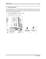
Page 26: ...out diagram is shown in Chapter 1 for all the position of connectors and headers on the board that you may refer to WARNING Always power off the computer and unplug the AC power cord before adding or removing any peripheral or component Failing to so may cause severe damage to your motherboard and or peripherals Plug in the AC power cord only after you have carefully checked everything ATX Power I...

Page 27: ...stalled in your system The CPU must be kept cool by using a powerful fan with heatsink The system is capable of monitoring the speed of the CPU fan CPUFAN1 CPU Fan PWRFAN1 Power Fan CASFAN1 Case Fan WARNING These fan connectors are not jumpers DO NOT place jumper caps on these connectors User s Manual ...

Page 28: ...emory if the settings in the BIOS Setup Utility are incorrect and prevents your motherboard from operating To clear the CMOS memory disconnect all the power cables from the motherboard and then move the jumper cap into the CLEAR setting for a few seconds Pin 1 2 shorted default Normal operation Pin 2 3 shorted Clear CMOS memory SG 72 ...

Page 29: ...ect Disabled setting if you are going to update your BIOS After updating the BIOS return it to the default Write Protect Enabled setting Make sure to disconnect all the power cables from the motherboard before changing the BIOS protection setting Pin 1 2 shorted Default Write Protect Enabled Pin 2 3 shorted Write Protect Disabled User s Manual ...

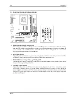
Page 30: ...omentary contact switch that is normally open When the switch is closed the board resets and runs POST MSGLED Power Sleep Message Waiting LED Connecting pins 2 and 4 to a single or dual color front panel mounted LED provides power on off sleep and message waiting indication PWRSW Power Switch Supporting the power on off function requires connecting pins 6 and 8 to a momentary contact switch that i...

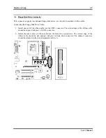
Page 31: ...one end of the ribbon cable into the FDC1 connector The colored edge of the ribbon cable should be aligned with pin 1 of FDC1 connector 2 Install the other end s of ribbon cable into the disk drive connector s The colored edge of the ribbon cable should be also aligned with pin 1 of disk drive connector The endmost connector should be attached to the drive designated as Drive A User s Manual ...

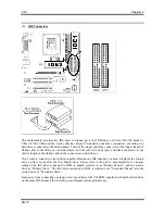
Page 32: ...bbon cable to the connectors on hard drives If you want to connect two hard drives together through one IDE channel you must configure the second drive to Slave mode after the first Master drive Please refer to the drives documentation for jumper settings The first drive connected to IDE1 is usually referred to as Primary Master and the second drive as Primary Slave The first drive connected to ID...

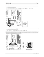
Page 33: ...nnect to the audio output of internal CD ROM drive or add on card 9 Accelerated Graphics Port Slot This slot supports an optional AGP graphics card up to 4X 8X mode ATTENTION This motherboard does not support 3 3V AGP cards Use only 1 5V or 0 8V AGP cards User s Manual ...

Page 34: ...d USB ports USB1 USB2 at the rear edge I O port array you can add two additional USB ports by connecting extension cables to these headers USB3 USB4 Pin Pin Assignment Pin Pin Assignment 1 VCC 2 VCC 3 Data0 4 Data1 5 Data0 6 Data1 7 Ground 8 Ground 9 NC 10 NC SG 72 ...

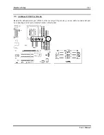
Page 35: ...p 2 13 11 Additional COM2 Port Header Besides the onboard serial port COM1 at the rear edge I O port array you can add a second serial port by connecting a serial port extension bracket to this header User s Manual ...

Page 36: ...t panel remove all the jumpers on this header and then connect to front panel by the extension cable provided with the chassis To use the audio connector at rear panel disconnect the extension cable attach the jumpers back at pin 5 6 and pin 9 10 default setting Pin Pin Assignment Pin Pin Assignment 1 Audio Mic 2 Ground 3 Audio Mic Bias 4 VCC 5 Speaker Out Right Channel 6 Speaker Out Right Channel...

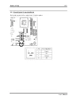
Page 37: ...Hardware Setup 2 15 13 Chassis Speaker Connection Header This header connects to the computer case s built in speaker Pin Pin Assignment 1 Signal 2 NC 3 Ground 4 5V User s Manual ...

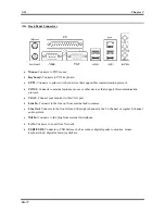
Page 38: ...is communication protocol VGA1 Connect your monitor to this VGA port Line In Connects to the line out from external audio sources Line Out Connects to the front left and front right channel in the 5 1 channel or regular 2 channel audio system Mic In Connects to the plug from external microphone LAN Connects to Local Area Network USB1 USB2 Connects to USB devices such as scanner digital speakers mo...

Page 39: ...e memory count begins and then the following message appears on the screen PRESS DEL TO ENTER SETUP If this message disappears before you respond restart the system by pressing Ctrl Alt Del keys or by pressing the Reset button on computer chassis Only when it failed by these two methods can you restart the system by powering it off and then back on After pressing Del key the main menu screen appea...

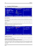
Page 40: ... submenu IDE HDD Auto Detection This item allows you to detect the parameters of IDE drives by pressing Enter key The parameters will be shown on the screen automatically IDE Channel 0 Master Slave and IDE Channel 1 Master Slave When set to Auto the BIOS will automatically check what kind of IDE drive you are using If you want to define your own drive by yourself set it to Manual and make sure you...

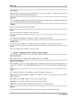
Page 41: ...figures the numbers of sectors per track Back to Standard CMOS Features Setup Menu Drive A Drive B This item sets the type of floppy drives usually only Drive A installed Floppy 3 Mode Support This item allows you to use 3 Mode Floppy Drive in Japanese computer system by selecting drive A B or both Leave this item to its default Disabled setting if you are not using this Japanese standard floppy d...

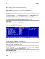
Page 42: ...0K or more memory size installed on the motherboard Extended Memory This item displays the amount of extended memory detected during system boot up Total Memory This item displays the total memory available in the system 3 2 Advanced BIOS Features CPU Feature This item is used to manage the thermal issue for certain CPU Hard Disk Boot Priority Use this option to select the hard disk boot priority ...

Page 43: ...ether the floppy disk drive is installed or not Boot Up NumLock Status This item determines the default state of the numeric keypad at system booting up On The numeric keypad functions as number keys Off The numeric keypad functions as arrow keys Security Option This item determines when the system will prompt for password every time the system boots or only when enters the BIOS setup Setup The pa...

Page 44: ...nd will cause malfunction 3 3 Advanced Chipset Features DRAM Timing Control Click Enter key to enter its submenu Memory Timing Enables you to select the CAS latency time in HCLKs of 2 2 5 or 3 The value is set at the factory depending on the DRAM installed Do not change the values in this field unless you change specifications of the installed DRAM or the installed CPU CAS Latency Time This item c...

Page 45: ...about the same as the RAM Access data read write time RAS to CAS Delay tRCD This is the amount of time a CAS is performed after a RAS The lower the better but some DRAM does not support low figures Back to Advanced Chipset Features Setup Menu AGP P2P Bridge Control Click Enter key to enter its submenu AGP Aperture Size This setting controls just how much system RAM can be allocated to AGP for vide...

Page 46: ...B is borrowed which in the meanwhile the same the main memory loses Back to Advanced Chipset Features Setup Menu System BIOS Cacheable This item allows the system to be cached in memory for faster execution Enable this item for better performance Video RAM Cacheable These items allow the video BIOS and RAM to be cached in memory for faster execution Enable these items for better performance 3 4 In...

Page 47: ...der the DOS environment IDE Burst Mode This option when enabled will instruct the system to send every write transaction to the write buffer Burstable transactions then burst onto the PCI bus and nonburstable transactions do not Back to Integrated Peripherals Setup Menu OnChip PCI Device Click Enter key to enter its submenu USB Controller This item enables the USB controller Leave this at the defa...

Page 48: ...em if you are going to install a PCI audio add on card Back to Integrated Peripherals Setup Menu Onboard SuperIO Device Click Enter key to enter its submenu Onboard FDD Controller This option enables the onboard floppy disk drive controller Onboard Serial Port 1 This option is used to assign the I O address and interrupt request IRQ for onboard serial port 1 COM1 Onboard Serial Port 2 This option ...

Page 49: ...ECP aware peripherals ECP Mode Use DMA When the onboard parallel port is set to ECP mode the parallel port can use DMA 3 or DMA 1 Back to Integrated Peripherals Setup Menu Onboard PCI Device Click Enter key to enter its submenu Onboard LAN Device Enables and disables the onboard LAN LAN Boot ROM Use this item to enable and disable the booting from the onboard LAN or a network add in card with a re...

Page 50: ...hat is controlled by the power button on your system If the item is set to Instant Off then the power button causes a software power down If the item is set to Delay 4 Sec then you have to hold the power button down for four seconds to cause a software power down Restore On AC Power Loss This item selects the system action after an AC power failure Power Off When power returns after an AC power fa...

Page 51: ...y whether the system will be awakened from power saving modes when activity or input signal of the specified hardware peripheral or component is detected PS2KB Wakeup from S3 This option allows you to set hot key combination to turn on the system by keyboard PS2MS Wakeup from S3 This option allows you to set the mouse action to turn on the system Wakeup by Alarm When set to Enabled the following t...

Page 52: ...ata contains the IRQ DMA I O port memory information of the system This is a specification and a feature specific to the Plug Play BIOS IRQ Resources Click Enter key to enter its submenu This item sets each system interrupt to either PCI Device or Reserved Back to PnP PCI Configurations Setup Menu PCI VGA Palette Snoop This item determines whether the MPEG ISA VESA VGA cards can work with PCI VGA ...

Page 53: ...item only works for the OS with ACPI activated All Voltages Fans Speed and Thermal Monitoring These unchangeable items list the current status of the CPU and environment temperatures fan speeds and system power voltage NOTE The hardware monitoring features for temperatures fans and voltages will occupy the I O address from 294H to 297H If you have a network adapter sound card or other add on cards...

Page 54: ...manually 3 9 Load Fail Safe Defaults This option loads the BIOS default values for the most stable minimal performance system operations 3 10 Load Optimized Defaults This option loads the BIOS default values that are factory settings for optimal performance system operations 3 11 Set Password This option protects the BIOS configuration or restricts access to the computer itself 3 12 Save Exit Setu...

Page 55: ...vers Utilities CD that came packaged with your board The display shown in the following figure should appear after inserting this CD into your CD ROM drive if not enter My Computer CD ROM Drive double click autorun exe Please follow the on screen instruction to complete the driver installation User s Manual ...

Page 56: ...river Install RealTek 6 Channel AC 97 CODEC driver for Windows Operating System RealTek LAN Driver Install RealTek LAN driver for Windows Operating System USB 2 0 Driver Install USB 2 0 driver for Windows Operating System Manual View the user s manual in PDF file Utility Click to enter a sub screen for installing Acrobat Reader DirectX and Award BIOS Flash Utility software Browse CD Browse the con...

Page 57: ...est the following three troubleshooting methods to discharge CMOS data recover the hardware default status and then make the motherboard working again No need to bother returning the motherboard to where you bought from or go through an RMA process Step 1 Switch off the power supply unit and then switch it on again after one minute If there is no power switch on the power supply unit disconnect it...

Page 58: ... try to start the system each time you insert a card until the system will not start Keep the VGA card and the interface card that caused the problem inserted on the motherboard remove any other cards or peripheral and start again If you still cannot start note the information related to both cards in the add on Card space provided and don t forget to indicate the motherboard model version BIOS id...

Page 59: ...mple In the HDD space check the box in the Brand space write Seagate in the Specifications space write ST31621A 1 6GB 8 CD ROM Drive Indicate the brand and specifications of your CD ROM drive Specify if it uses IDE1 or IDE2 and check in case you give no indication we will consider that your CD ROM is IDE2 Master Example In the CD ROM drive space check the box in the Brand space write Mitsumi in th...

Page 60: ...Name Phone Number Contact Person Fax Number E mail Address Model BIOS ID Motherboard Model No DRIVER REV OS Application Hardware Name Brand Specifications CPU HDD IDE1 IDE2 CD ROM Drive IDE1 IDE2 System Memory ADD ON CARD Problem Description SG 72 ...

Page 61: ...ts have the best quality and compatibility In case you need service or technical support please understand the constraint we have and always check with the reseller who sold the product to you first To expedite service we recommend that you follow the procedures outlined below before contacting us With your help we can meet our commitment to provide the best service to the greatest number of ABIT ...

Page 62: ...integrated and sold the system to you They should know best what your system configuration is and your problem They should have reasonable return or refund policies How they serve you is also a good reference for your next purchase 6 Contacting ABIT If you feel that you need to contact ABIT directly you can send email to the ABIT technical support department First please contact the support team f...

Page 63: ...Bosnia Serbia and Macedonia Asguard Computer Ges m b H Schmalbachstrasse 5 A 2201 Gerasdorf Wien Austria Tel 43 1 7346709 Fax 43 1 7346713 asguard asguard at Japan ABIT Computer Japan Co Ltd Fax 81 3 5396 5110 http www abit4u jp Shanghai ABIT Computer Shanghai Co Ltd Tel 86 21 6235 1829 Fax 86 21 6235 1832 http www abit com cn Russia ABIT Computer Russia Co Ltd Fax 7 095 937 2837 techrussia abit c...

Page 64: ...ported to us giving detailed system configuration information and error symptoms will receive the highest priority For the other questions we regret that we may not be able to reply directly But your questions may be posted to the Internet news group in order that a larger number of users can have the benefit of the information Please check the news group from time to time 9 The information listed...

Reviews: