


Hardware Setup
2-3
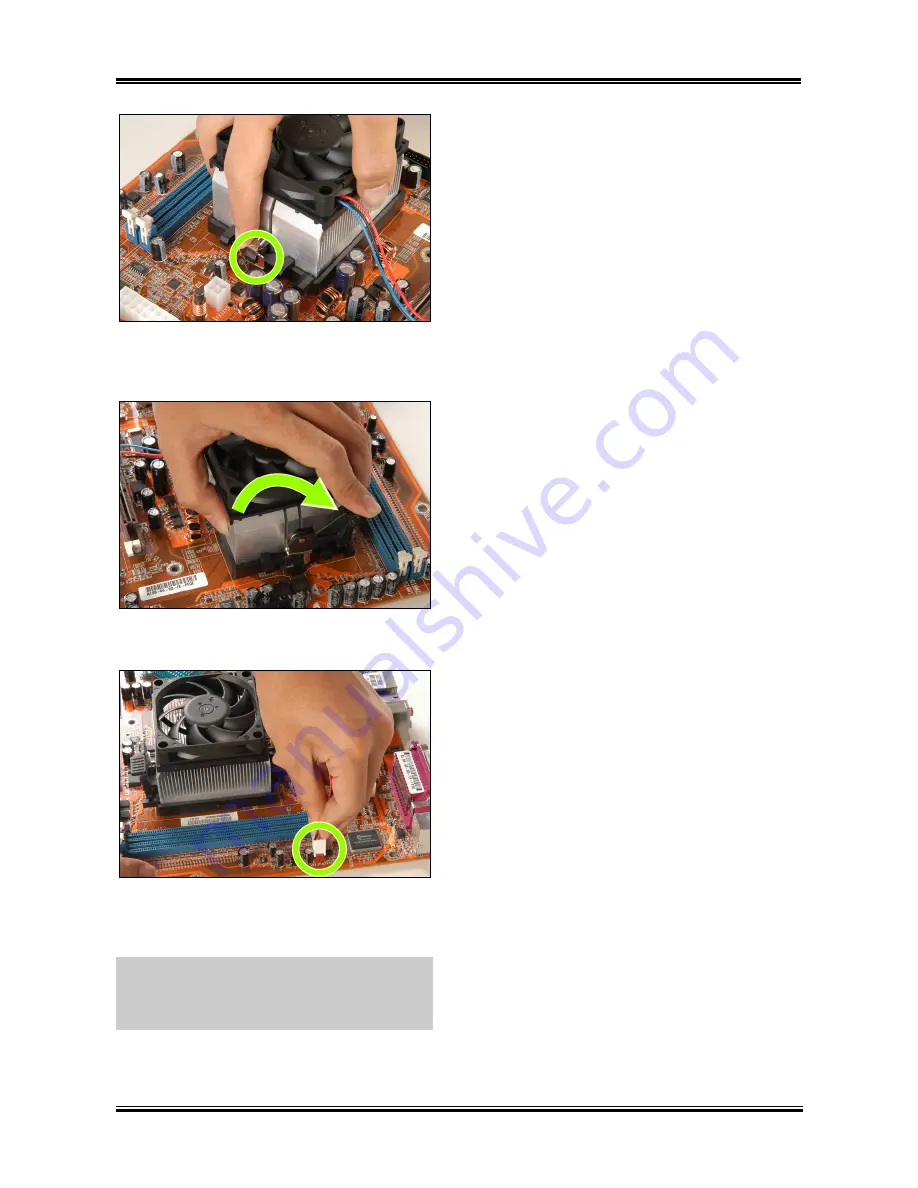
6.
On the other side, push the retention clip
straight down to lock into the plastic lug on the
retention frame.
7.
Turn the cam lever to lock into the retention
frame.
8.
Attach the four-pin power plug from the
heatsink and fan assembly to the CPU FAN
connector.
For detailed information on how to install your
heatsink and fan assembly, please refer to the
instruction manual came packed with the
heatsink and fan assembly you bought.
User’s Manual
Summary of Contents for NF8 Pro
Page 7: ...Introduction 1 3 1 2 Layout Diagram NF8 Pro NF8 NF8 V Pro NF8 V User s Manual ...
Page 8: ...1 4 Chapter 1 1 3 Layout Diagram NF8 V2 NF8 Series ...
Page 50: ...3 24 Chapter 3 3 24 Chapter 3 NF8 Series NF8 Series ...
Page 54: ...B 2 Appendix B B 2 Appendix B NF8 Series NF8 Series ...
Page 56: ...C 2 Appendix C C 2 Appendix C NF8 Series NF8 Series ...
Page 64: ...G 2 Appendix G G 2 Appendix G NF8 Series NF8 Series ...